
Impreza RS Coupe AWD F4-2.5L SOHC (1999)
10. If necessary, adjust the valve clearance.
11. Similar to measurement procedures used for #1 cylinder, measure #2, #3 and #4 cylinder valve clearances.
NOTE:
-
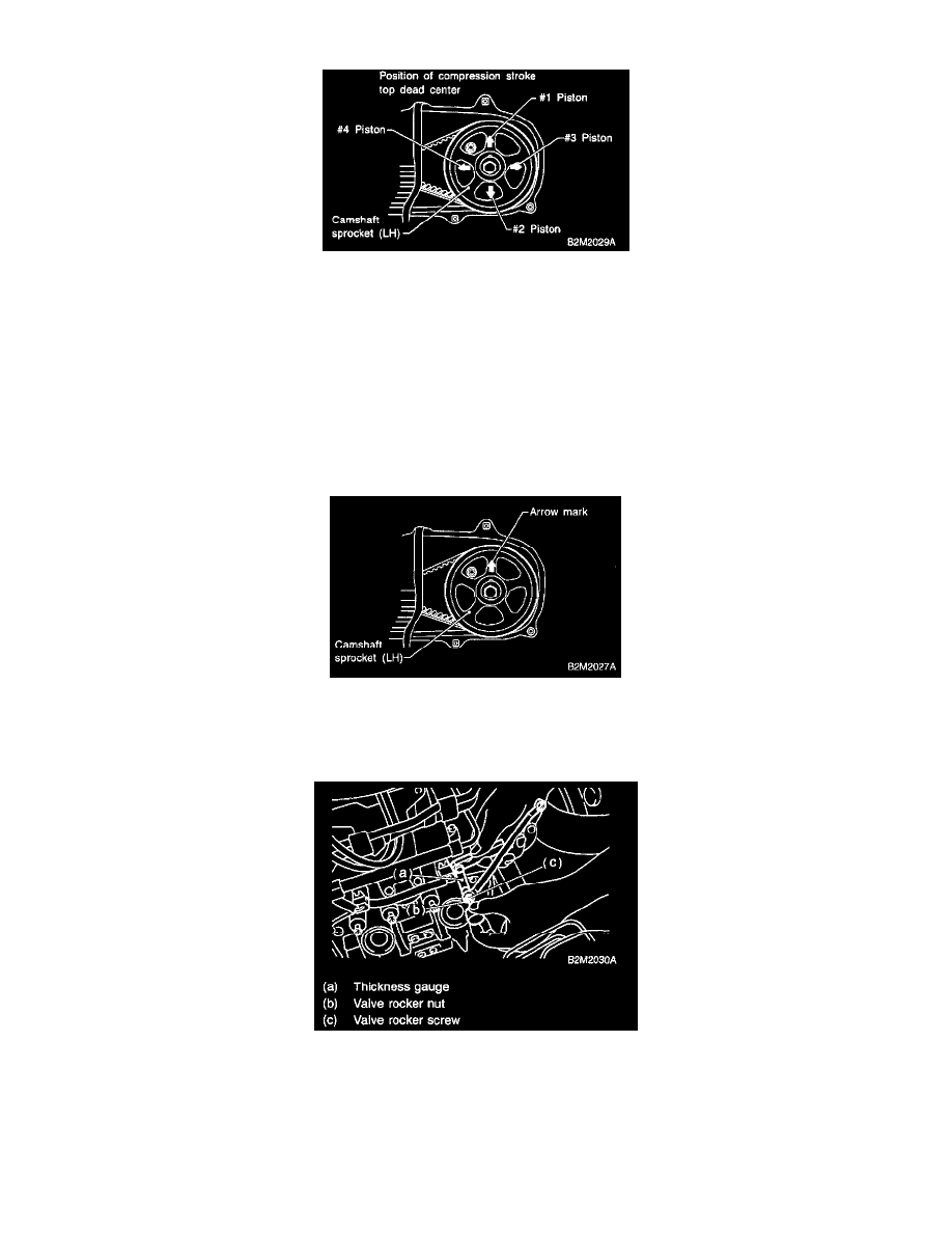
Be sure to set cylinder pistons to their respective top dead centers on the compression stroke before measuring valve clearances.
-
To set #3, #2 and #4 cylinder pistons to their top dead centers on the compression stroke, turn crankshaft pulley clockwise 90° at a time
starting with arrow mark on left-hand camshaft sprocket facing us.
12. After inspection, install the related parts in the reverse order of removal.
B: ADJUSTMENT
CAUTION: Adjustment of valve clearance should be performed while engine is cold.
1. Set #1 cylinder piston to top dead center of compression stroke by rotating crankshaft pulley clockwise.
NOTE: When arrow mark on camshaft sprocket (LH) comes exactly to the top, #1 cylinder piston is brought to the top dead center of the
compression stroke.
2. Adjust the #1 cylinder valve clearance.
1. Loosen the valve rocker nut and screw.
2. Place suitable thickness gauge.
3. While noting valve clearance, tighten valve rocker adjust screw.
4. When specified valve clearance is obtained, tighten valve rocker nut.
Tightening torque: 10 ± 1 Nm (1.0 ± 0.1 kg-m, 7.2 ± 0.7 ft. lbs.)
CAUTION: