
Legacy F6-3.0L (2005)
19. Insert the valve assembly into place while facing rack teeth toward pinion.
20. Tighten the bolts alternately to secure valve assembly.
Tightening torque: 20 Nm (2.0 kgf-cm, 14.8 ft. lbs.)
CAUTION: Be sure to alternately tighten the bolts.
21. Apply liquid gasket to at least 1/3 of the entire perimeter of adjusting screw thread.
Liquid gasket: THREE BOND 1141 (Part Not 004403006)
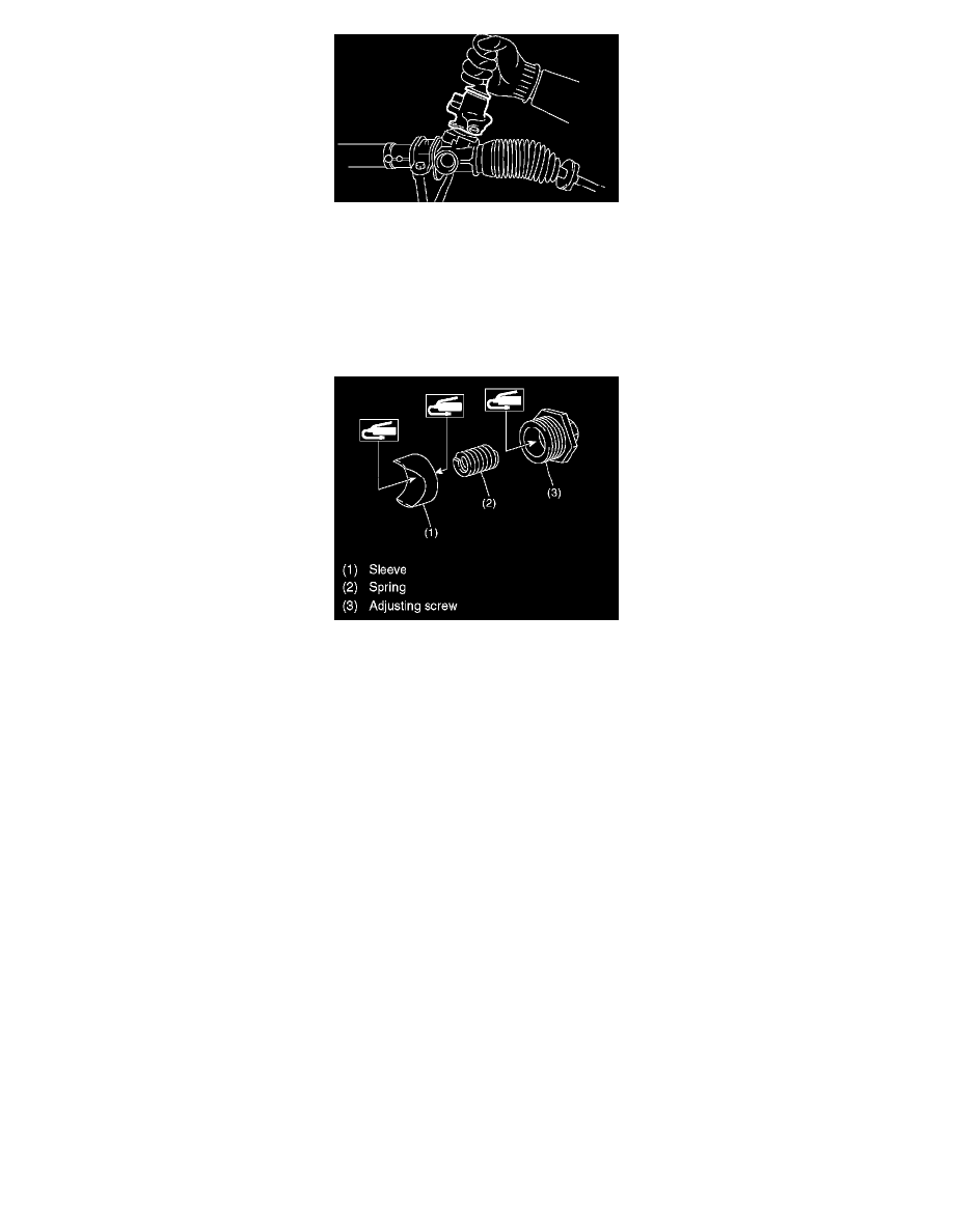
22. Apply a coat of grease to the sliding surface of sleeve and seating surface of spring, and then insert the sleeve into steering body.
Charge the adjusting screw with grease, and then insert the spring into adjusting screw and install on steering body.
23. Tighten the adjusting screw with specified torque.
Tightening torque: 3.9 Nm (0.4 kgf-cm, 2.9 ft. lbs.)
24. After tightening to the specified tightening torque, loosen it by 20°.
25. Adjust the turning resistance of gearbox so that it is within specification using adjusting screw.
26. Apply liquid gasket to lock nut and install it into adjusting screw. While holding the adjusting screw with a wrench, tighten the lock nut using ST.
Liquid gasket:
THREE BOND 1141 ST 926230000 SPANNER
Tightening torque (Lock nut): 25 Nm (2.5 kgf-cm, 18.1 ft. lbs.)
NOTE: Hold the adjusting screw with a wrench to prevent it from turning while tightening lock nut.
27. Remove the gearbox from ST.
ST1 926200000 STAN D
ST2 34199AG000 BOSS D
28. Install the four pipes on gearbox.
1. Connect the pipe A and B to the gearbox.
Tightening torque: Refer to COMPONENT.