
Legacy Brighton Wagon AWD F4-2.5L SOHC (2000)
10. Remove bolt and then disconnect lever upper and lever lower.
C: INSPECTION
1. Inspect removed parts by comparing with new ones for deformation, damage and wear. Correct or replace if defective.
2. Confirm the following parts for operating condition before assembly. Moving condition of the selector lever upper, it should move smoothly.
D: ASSEMBLY
1. Clean all parts before assembly.
2. Apply grease [MULTEMP AC-D or equivalent] to each parts.
3. Assembly is in the reverse order of disassembly.
4. After completion of fitting, transfer selector lever to range "P" - "1", then check whether the indicator and selector lever agree, whether operating
force is.
E: INSTALLATION
1. Mount the selector lever onto the vehicle body.
2. Tighten the four bolts to install the selector lever to the vehicle body, then connect connector.
Tightening torque: 13 ± 3 Nm (1.3 ± 0.3 kg-m, 9.4 ± 2.2 ft. lbs.)
3. Install console box.
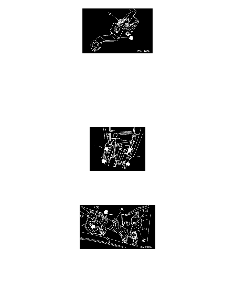
4. Set location of selector lever at "N" position.
5. Set location of selector arm installed on the transmission body at "N" position.
6. Pass cable (B) through selector arm pin and then connect it using a washer and snap pin (A).
7. Attach cable clamp (D) to transmission case with the bolts.
Tightening torque: 24.5 ± 2.0 Nm (2.50 ± 2 kg-m, 18.1 ± 1.4 ft. lbs.)
8. Insert the thread portion of the other inner cable and into the connector hole of the selector lever, and fix the other outer cable end to the bracket.
9. Adjust the inner cable length.
1. Put connector into contact with nut (A).