
Legacy GT LTD Sedan AWD F4-2.5L SOHC (2001)
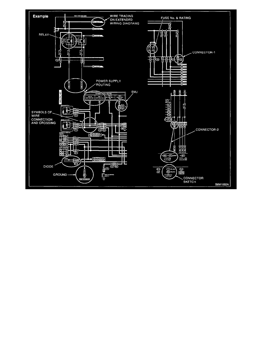
SYMBOLS IN WIRING DIAGRAMS
A number of symbols are used in each wiring diagram to easily identify parts or circuits.
1. RELAY
A symbol used to indicate a relay.
2. CONNECTOR-1
The sketch of the connector indicates the one-pole types.
3. WIRING CONNECTION
Some wiring diagrams are indicated in foldouts for convenience. Wiring destinations are indicated where necessary by corresponding symbols (as
when two pages are needed for clear indication).
4. FUSE NO. & RATING
The "FUSE No. & RATING" corresponds with that used in the fuse box (main fuse box, fuse and joint box).
5. CONNECTOR-2
-
Each connector is indicated by a symbol.
-
Each terminal number is indicated in the corresponding wiring diagram in an abbreviated form.
-
For example, terminal number "C2" refers to No. 2 terminal of connector (C:F41) shown in the connector sketch.
6. CONNECTOR SKETCH
-
Each connector sketch clearly identifies the shape and color of a connector as well as terminal locations. Non-colored connectors are indicated
in natural color.
-
When more than two types of connector number are indicated in a connector sketch, it means that the same type connectors are used.