
Legacy L Wagon AWD F4-2.2L SOHC (1997)
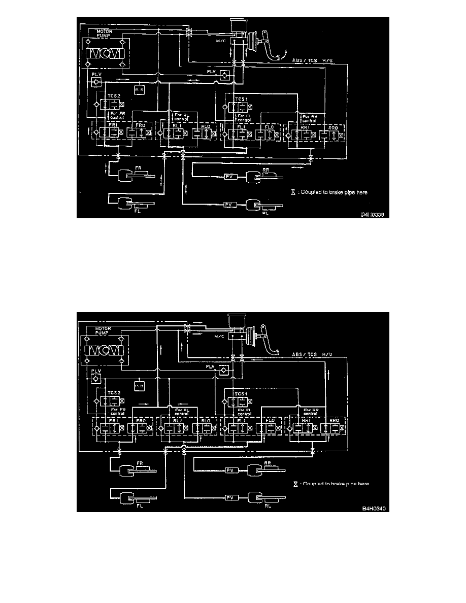
1) Normal Conditions (non-ABS control operation).
When the Hydraulic control Unit (H/U) solenoid valves and motor are not operating, the section from the Master Cylinder (M/C) to the Wheel
Cylinder (W/C) is open (inlet valve open) and the section from the W/C to the M/C reservoir is closed (outlet valve closed). Also, the special
valve is open.
When the brake pedal is depressed, the fluid pressure produced by the master cylinder is applied -in the primary system- from TCS1 to FR W/C
via FRI and to RL W/C via RLI. At the same time, in the secondary system, the fluid pressure is applied from TCS2 to FL W/C via FLI and to RR
W/C via RRI.
When the brake pedal is released, the fluid pressure at each W/C flows back through the same channels and is released. Since the FRI and FIJI
channels constrict the oil flow, they are provided with check valves from which the pressure is also released at this time.
2) Pressure-drop conditions.
In order to eliminate the fluid pressure acting on the W/C and release excessive brake force, the inlet valve is ON (closed) and the outlet valve is
ON (open), resulting in pressure-drop conditions. Figure shows hydraulic oil channels under these conditions (FRI, FRO--RRI, PRO all under
pressure-drop conditions).
Under these conditions the section between the M/C and W/C is closed and the section between the W/C and M/C reservoir is opened by solenoid
valve switching. The fluid pressure entering the W/C from the M/C pressure chamber is released by the M/C reservoir, and the W/C pressure drops
because of the pressure-drop conditions illustrated below.