
Legacy L Wagon AWD F4-2.2L SOHC (1997)
(F40) No.3 - (F29) No.2 / 10 ohms, max.
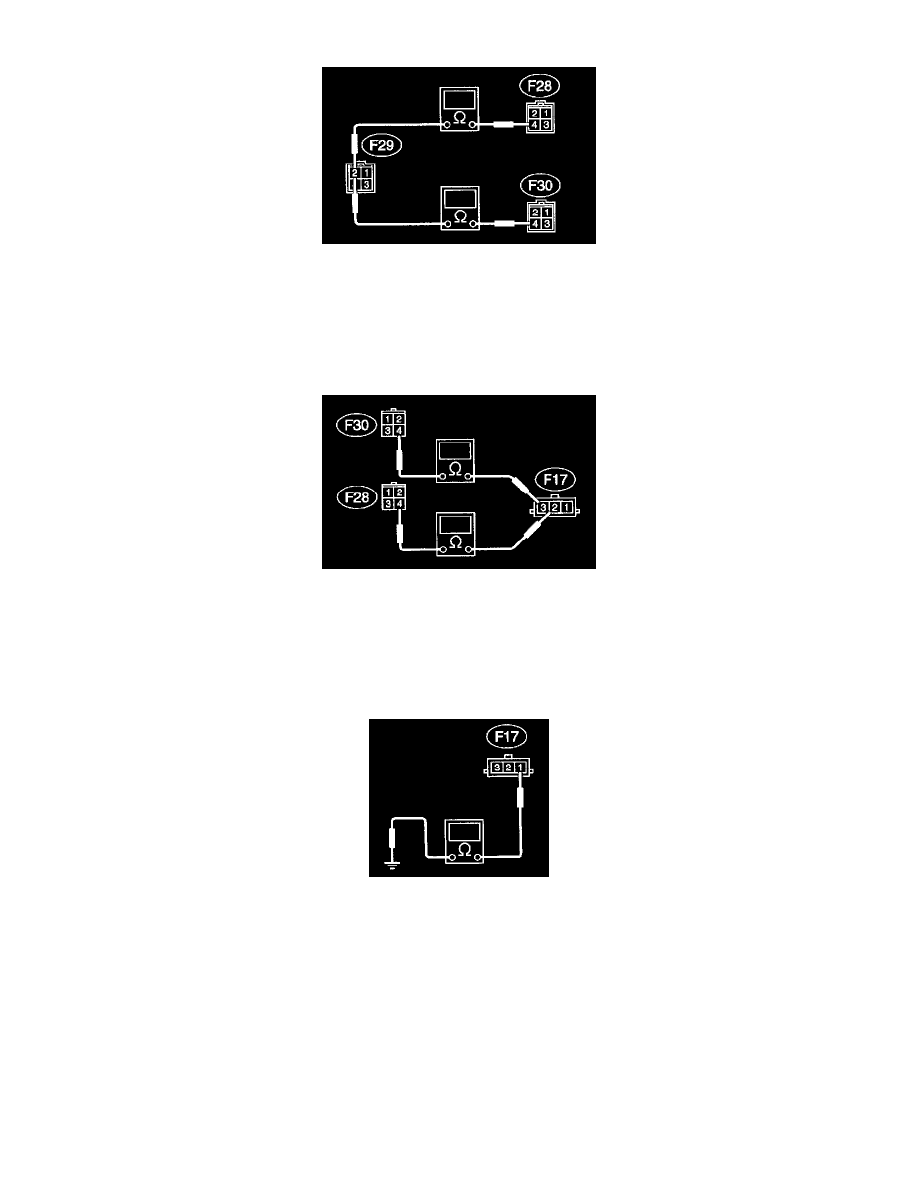
3. CHECK A/C RELAY HOLDER.
1) Disconnect connector from A/C relay holder.
2) Measure resistance between terminals of A/C relay holder.
Connector & terminal / Specified resistance:
(F29) No.2 - (F28) No.4 / 10 ohms, max.
(F29) No.2 - (F30) No.4 / 10 ohms, max.
4. CHECK HARNESS CONNECTOR BETWEEN A/C RELAY HOLDER AND MAIN FAN MOTOR.
1) Disconnect connectors from A/C relay holder and main fan motor.
2) Measure resistance of harness connector between A/C relay holder and main fan motor.
Connector & terminal / Specified resistance:
(F28) No.4 - (F17) No.2 / 10 ohms max.
(F30) No.4 - (F17) No.3 / 10 ohms max.
5. CHECK GROUND CIRCUIT OF MAIN FAN MOTOR.
Measure resistance between main fan motor connector and body.
Connector & terminal / Specified resistance:
(F17) No.1 - Body / 10 ohms max.