
Legacy L Wagon AWD F4-2.2L SOHC (1997)
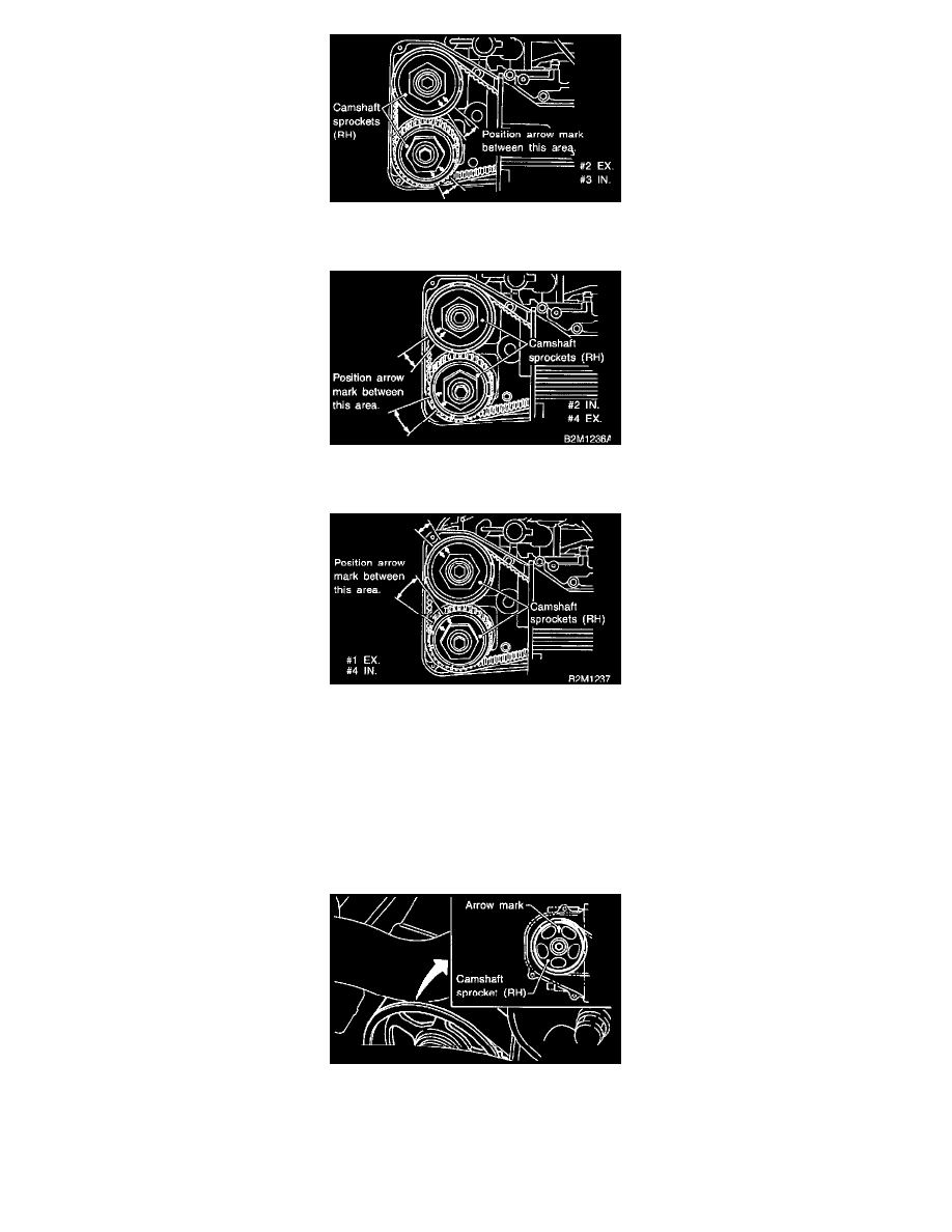
1) Set arrow mark on camshaft sprocket to position shown in figure, and measure #2 cylinder exhaust valve and #3 cylinder intake valve
clearances.
2) Set arrow mark on camshaft sprocket to position shown in figure, and measure #2 cylinder intake valve and #4 cylinder exhaust valve
clearances.
3) Set arrow mark on camshaft sprocket to position shown in figure, and measure #1 cylinder exhaust valve and #4 cylinder intake valve
clearances.
15) After inspection, install the related parts in the reverse order of removal.
B: ADJUSTMENT
1. 2200 cc Model
CAUTION: Adjustment of valve clearance should be performed while engine is cold.
1) Set #1 cylinder piston to top dead center of compression stroke by rotating crankshaft pulley clockwise.
NOTE: When arrow mark on camshaft sprocket (RH) comes exactly to the top, #1 cylinder piston is brought to the top dead center of
compression stroke.
2) Adjust the #1 cylinder valve clearance.
1) Loosen the valve rocker nut and screw.
2) Place suitable thickness gauge