
Legacy L Wagon AWD F4-2.2L SOHC (1997)
Control Arm: Service and Repair
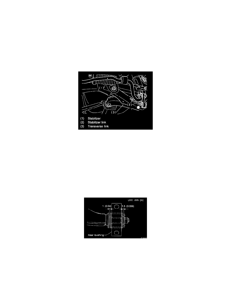
Installation
INSTALLATION
1) Temporarily tighten the two bolts used to secure rear bushing of the transverse link to body.
NOTE: These bolts should be tightened to such an extent that they can still move back and forth in the oblong shaped hole in the bracket (which
holds the bushing).
2) Install bolts used to connect transverse link to crossmember and temporarily tighten with nut.
CAUTION: Discard loosened self-locking nut and replace with a new one.
3) Insert ball joint into housing.
4) Connect stabilizer link to transverse link, and temporarily tighten bolts.
CAUTION: Discard loosened self-locking nut and replace with a new one.
5) Tighten the following points in the order shown below when wheels are in full contact with the ground and vehicle is at curb weight condition.
(1) Transverse link and stabilizer link
Tightening torque:
29 ± 5 Nm (3.0 ± 0.5 kg-m, 21.7 ± 3.6 ft.Ib.)
(2) Transverse link and crossmember
Tightening torque:
98 ± 15 Nm (10.0 ± 1.5 kg-m, 72 ± 11 ft.Ib.)
(3) Transverse link rear bushing and body
Tightening torque:
245 ± 49 N.m (25 ± 5 kg-m, 181 ± 36 ft.Ib.)
NOTE:
-
Move rear bushing back and forth until transverse link to-rear bushing clearance is established (as indicated in figure.) before tightening.
-
Check wheel alignment and adjust if necessary.