
Legacy L Wagon AWD F4-2.2L SOHC (1997)
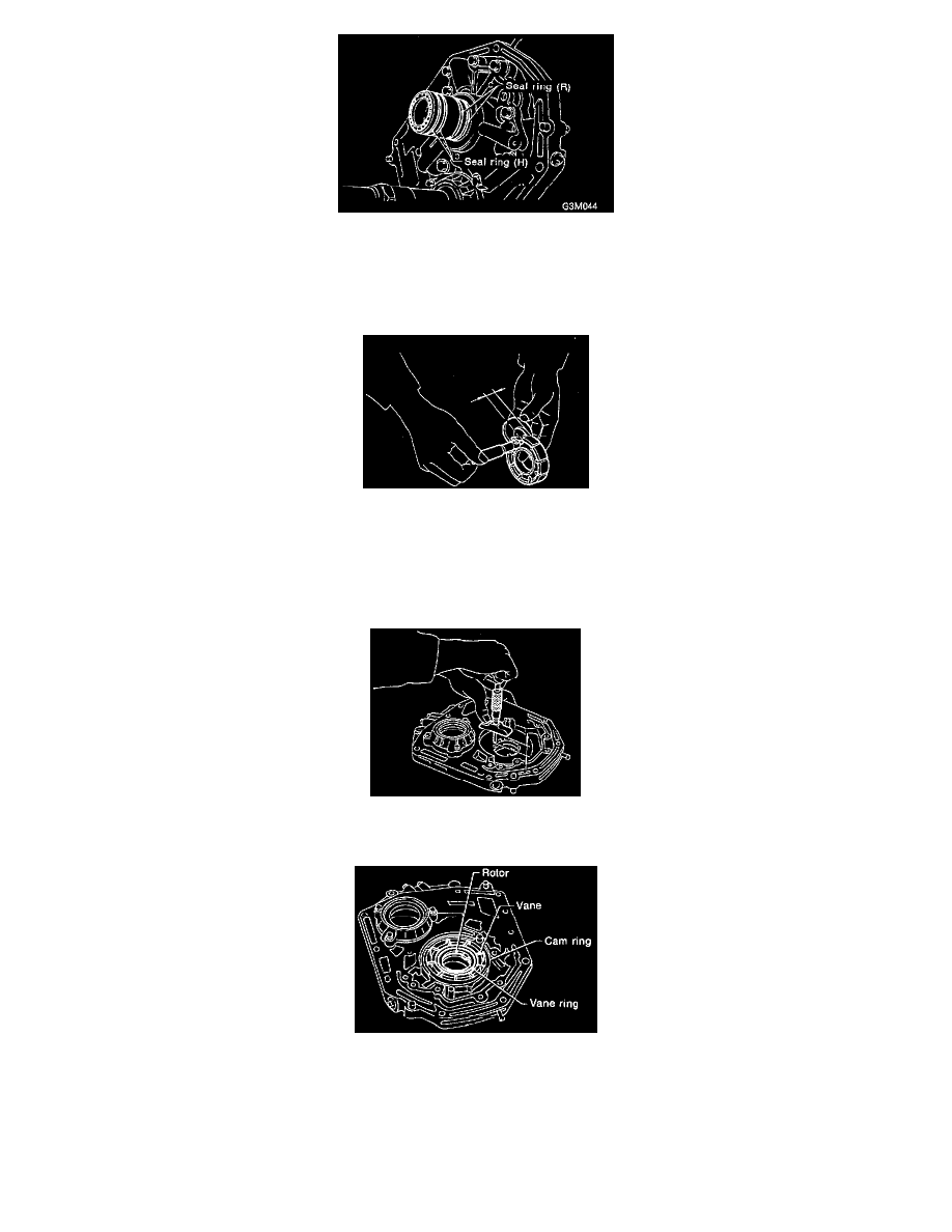
5. Remove two seal rings (R) and two seal rings (H).
INSPECTION
1. Make sure that each component is free of harmful gouges, cuts, and dust.
2. Selection of oil pump components (rotor, vanes, control piston and cam ring)
a. Using a micrometer, measure the height of the rotor, vanes, control piston and cam ring in at least four positions. (Measure the height at one
place for each of the nine vanes.)
NOTE:
-
Remove the control piston seals when measuring.
-
Remove the friction ring from the cam ring when measuring.
b. Using a depth gauge, measure the depth of the oil pump housing from the contact/sliding surface of the above mentioned component parts in
the same manner as above.
c. Make sure that the clearances are within the specified wear limits. If the wear limit is exceeded, select pump components so that the standard
clearance can be obtained.