
Legacy L Wagon AWD F4-2.2L SOHC (1997)
Shift Cable: Description and Operation
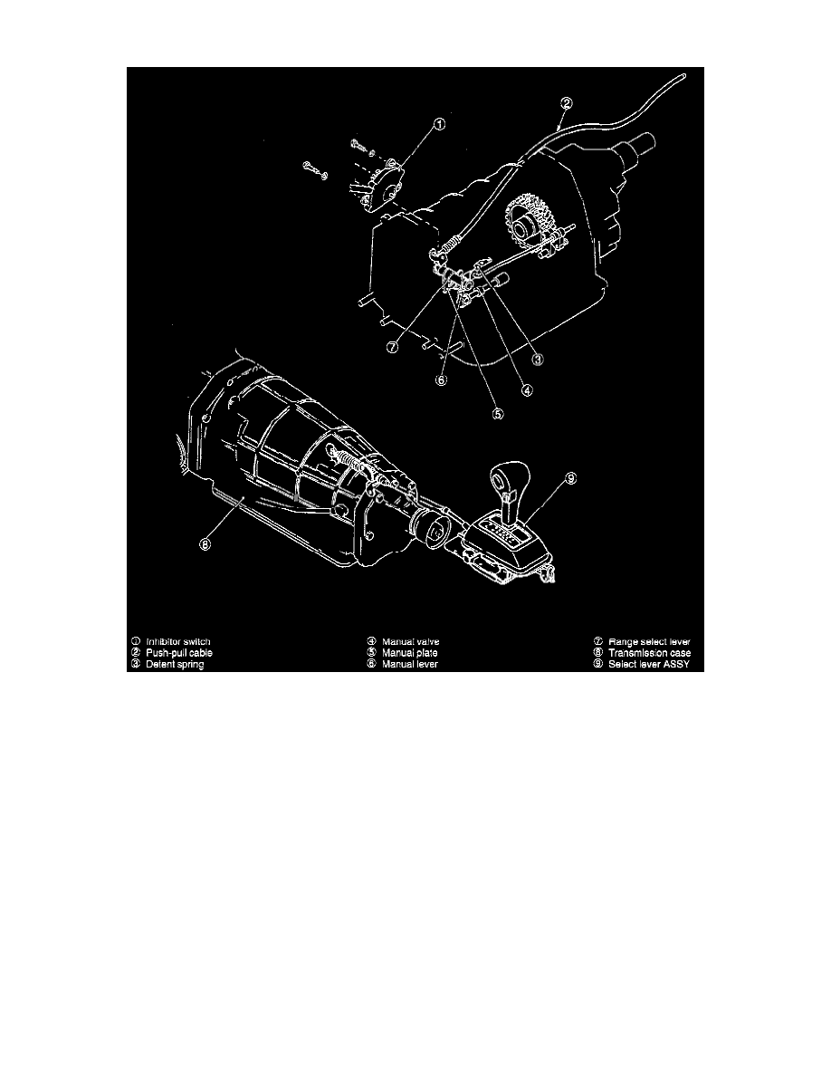
DESCRIPTION
The range select mechanism consists of a select lever (on the floor/center console in the driver's compartment), push-pull cable, linkages, manual
valve, parking pawl, etc.
OPERATION
When the select lever is moved either forward or backward, the push-pull cable moves in the corresponding direction. This turns the manual shaft
by way of the range select lever. At this point, the pin at the end of the range select lever turns the inhibitor switch arm to transmit a range signal to
the control module.
A manual plate and manual lever are attached to the manual shaft. The manual plate is fan-shaped and is provided with seven grooves on its edge
corresponding to shift ranges (from "P" to "1"). A detent spring roller fits into the groove corresponding to the range selected. This regulates effort
required to operate the select lever.
A hydraulically controlled manual valve is installed on the lower pin of the manual lever. It slides in response to rotation of the manual shaft,
thereby selecting an oil passage inside the lower valve body in response to the position (P, R, N, D, 3, 2 or 1 ) of the select lever.
A parking rod located on the upper portion of the lever mechanically holds the output shaft when the select lever is shifted to "P"