
Legacy Outback Wagon F4-2.5L SOHC (2000)
12
If necessary, adjust the valve clearance.
13
Similar to measurement procedures used for #1 cylinder, measure #2, #3 and #4 cylinder valve clearances.
NOTE:
^
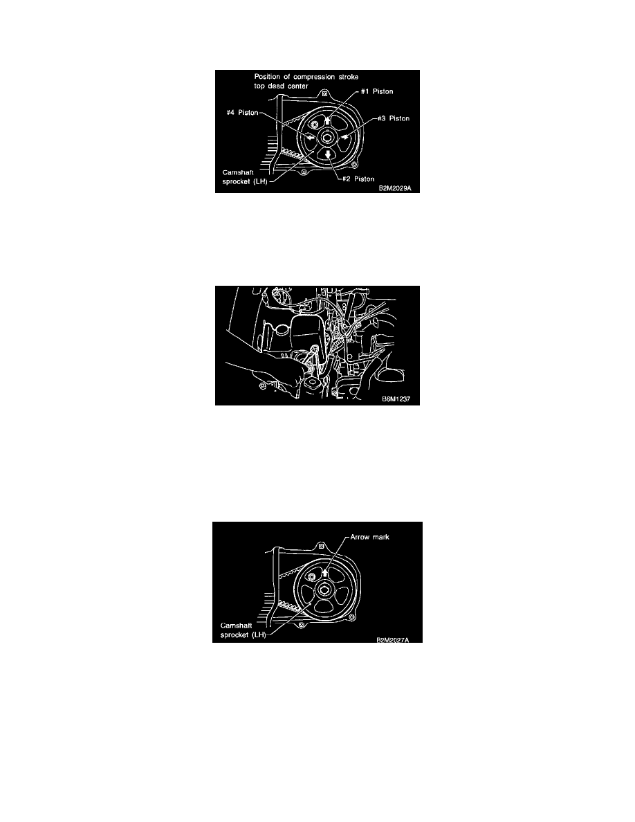
Be sure to set cylinder pistons to their respective top dead centers on compression stroke before measuring valve clearances.
^
To set #3, #2 and #4 cylinder pistons to their top dead centers on compression stroke, turn crankshaft pulley clockwise 180° at a time starting
arrow mark on left-hand camshaft sprocket facing up.
14
After inspection, install the related parts in the reverse order of removal.
Tightening torque:
^
Resonator Chamber, 32 +/- 10 Nm (3.3 +/- 1.0 kg-m, 24 +/- 7 ft-lb)
ADJUSTMENT
CAUTION: Adjustment of valve clearance should be performed while engine is cold.
1
Set #1 cylinder piston to top dead center of compression stroke by rotating crankshaft pulley clockwise.
Note: When arrow mark on camshaft sprocket (LH) comes exactly to the top, #1 cylinder piston is brought to the top dead center of compression
stroke.
2
Adjust the #1 cylinder valve clearance.
a
Loosen the valve rocker nut and screw.
b
Place suitable thickness gauge.
c
While noting valve clearance, tighten valve rocker adjust screw.
d
When specified valve clearance is obtained, tighten valve rocker nut.
Tightening Torque: 10 +/- 1 Nm (1.0 +/- 0.1 kg-m, 7.2 +/- 0.7 ft-lb)