
Legacy Postal Wagon AWD F4-2.2L SOHC (1998)
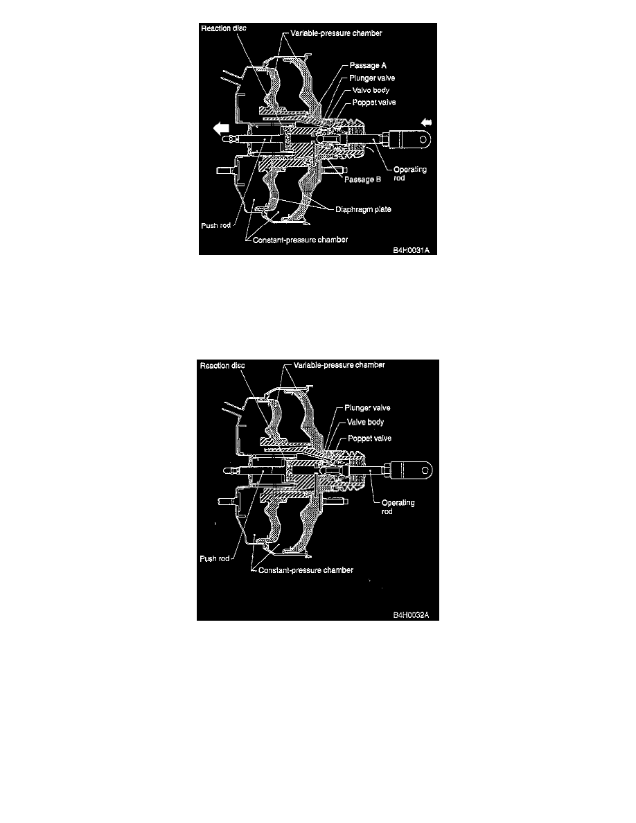
2. Brake booster "ON".
When the brake pedal is depressed, the operating rod pushes the plunger valve so that the poppet valve comes in contact with the vacuum valve of
the valve body. This shuts off the circuit between passages A and B. as well as the circuit between the constant- and variable-pressure chambers.
Further movement of the plunger valve moves the atmospheric valve away from it so that atmospheric air is directed to the variable-pressure
chamber via passage B. This produces a pressure differential between the constant- and variable-pressure chambers. As a result, the diaphragm and
its plate are moved to the left as a single unit. The power applied to the diaphragm plate by the pressure differential is then transmitted to the
reaction disc via a hub, as well as to the push rod, and produces a booster output.
3. Brake booster under medium load.
The poppet valve comes in contact with the plunger valve and valve body when a force pushes the center of the reaction disc (at the contact
portion of the plunger valve) via the operating rod and plunger valve. This occurs when brake pedal depression is balanced with a force pushing
the plunger valve (via the push rod and reaction disc) due to the reaction force of oil pressure delivered from the master cylinder.
As a result, pressure differential is maintained between the constant-pressure chamber and variable-pressure chamber unless the pedal depression
force is changed.