
Legacy Postal Wagon AWD F4-2.2L SOHC (1998)
EGR Temperature Sensor: Testing and Inspection
A faulty EGR temperature sensor will set code 55 in the on-board diagnostic system.
WIRE COLOR CODE IDENTIFICATION
L:
Blue
B:
Black
Y:
Yellow
G:
Green
R:
Red
W: White
Br: Brown
Lg: Light green
Gr: Gray
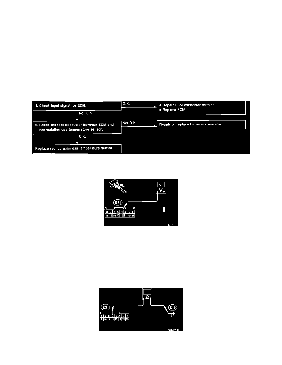
EGR TEMPERATURE SENSOR DIAGNOSTIC CHART
Diagnostic Chart
CHECK INPUT SIGNAL FOR ECM
Input Signal
1. Turn ignition switch "ON".
2. Measure voltage between ECM connector and ground as follows:
Connector & terminal:
Voltage:
(E31)4-Ground
4 - 4.8 Volts DC at 20°C (68°F)
(E31)4-Ground
0.4 - 1.2 Volts DC at 100°C (212°F)
CHECK HARNESS BETWEEN SENSOR AND ECM
Harness Test
1. Turn ignition switch "OFF".