
Legacy Postal Wagon AWD F4-2.2L SOHC (1998)
Transfer Control
The transfer hydraulic pressure control module is fitted with the transfer valve body attached to the side face of the extension case via gasket and
separate plate.
The hydraulic oil of the transfer hydraulic pressure control module is led from the oil pump delivery pressure circuit on the transmission case front to
the transmission case rear. From there it is further led to the extension case where it is fed to the hydraulic circuit of the transfer valve body.
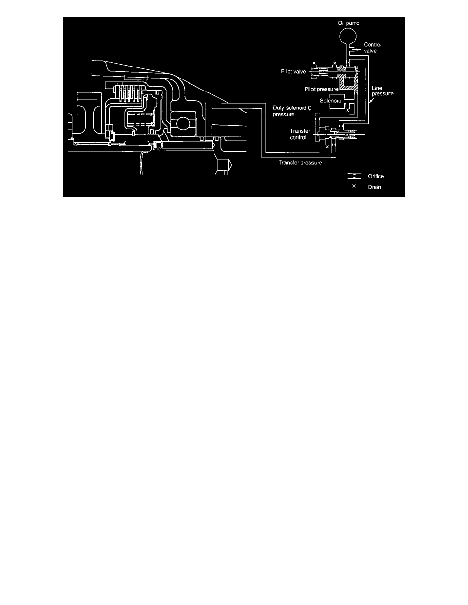
The hydraulic oil pressure (line pressure) is regulated by the transfer pilot valve, duty solenoid C and transfer control valve for obtaining optimum rear
torque distribution corresponding to the driving conditions.
1. The line pressure regulated to a proper pressure corresponding to the driving condition is further regulated to a constant pilot pressure by the
transfer pilot valve.
2. The pilot pressure is regulated to the transfer duty pressure by the duty solenoid C whose duty ratio is controlled by the TCM corresponding to the
driving condition. (The transfer duty pressure varies with the degree of duty control.)
3. The transfer duty pressure is applied to the transfer control valve.
4. The line pressure is led also to the transfer control valve where the pressure is regulated to the transfer clutch pressure by the transfer duty
pressure. (The transfer clutch pressure varies with the transfer duty pressure.)
5. The transfer clutch pressure is applied to the transfer clutch and causes the clutch to be engaged.
In this way, the transfer clutch pressure is varied so that optimum rear torque distribution can be achieved which corresponds to the vehicle driving
conditions.