
Legacy Postal Wagon AWD F4-2.2L SOHC (1998)
When oil temperature is below approximately 10°C (50°F), the vehicle cannot be shifted to the 4th range.
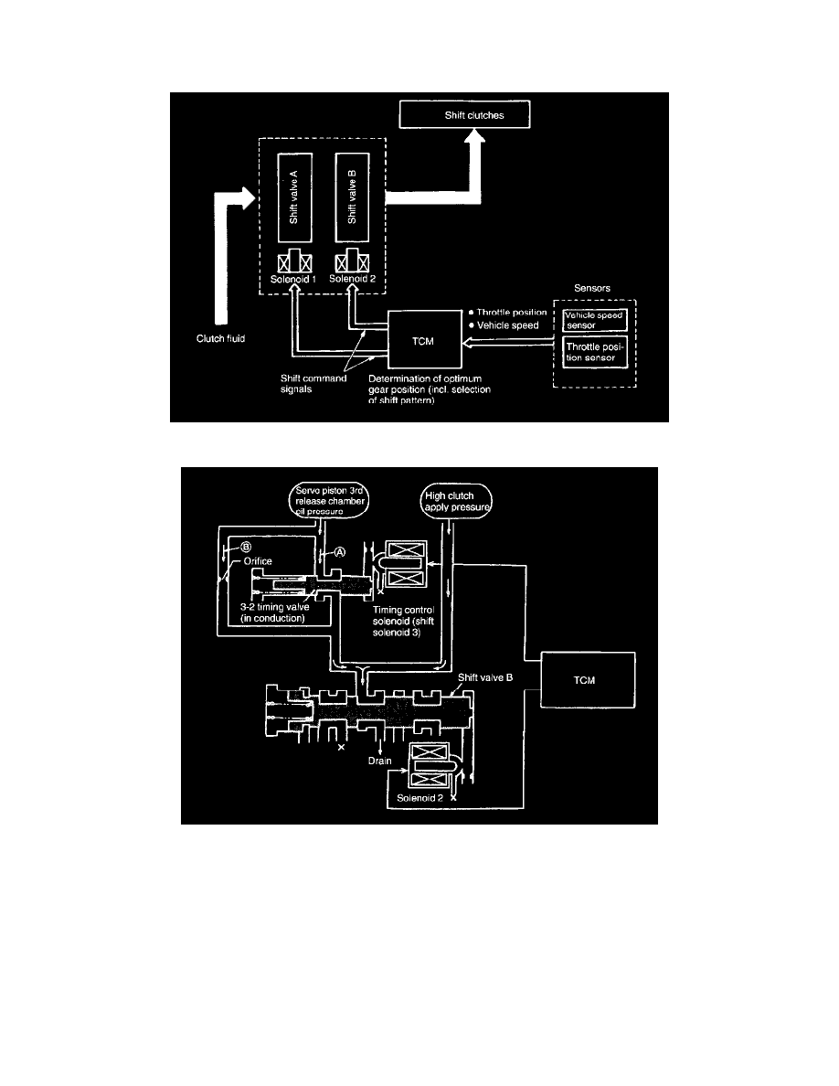
1. Control module activates both solenoids 1 and 2 in response to throttle and vehicle speed signals.
2. Shift valve moves in response to solenoid operation, supplying/interrupting clutch pressure to the line.
3. Gears are shifted by ON-OFF operation of both solenoids as indicated in Table.
3-2 Timing Control
When shifting from 3rd to 2nd, the high clutch is disengaged. At the same time, oil pressure (which releases the brake band) is also released from the
servo piston 3rd release chamber (3R).
At this point, the servo piston moves to release oil pressure from the 3rd release chamber (3R) and apply oil pressure to the 2nd apply chamber. This
causes the brake band to be applied. In other words, high clutch "release" and brake band "application" This eliminates engine rev-up under no load or
hesitation.
-
When the 3-2 timing valve conducts, oil pressure applied to the 3rd release chamber is quickly released through passage (A).
-
When the 3-2 timing valve does not conduct, oil pressure applied to the 3rd release chamber is slowly released through passage (B) (provided with
an orifice).
Lock-Up Control
The lock-up engaging and disengaging conditions are set for each gear shift range, gear position and shift pattern and correspond to the throttle
position and vehicle speed, and the duty solenoid is electronically controlled by TCM controls the lock-up clutch. The lock-up clutch engagement and