
Legacy Postal Wagon AWD F4-2.2L SOHC (1998)
disengagement are controlled by the lock-up control valve.
<When engaging and disengaging>
The shuttle shift valve D is actuated by the hydraulic pressure from the shift valve A. It controls the position of the lock-up control valve for engaging
or disengaging the lock-up clutch.
1. Non-lock-up operation (1st, N, R, and P range)
Since no operating pressure is generated from the shift valve A, the shuttle shift valve D sets the lock-up control valve in the "disengaging"
position.
The lock-up operating pressure (torque converter clutch regulator pressure) acts on the lock-up clutch disengaging circuit, while the engaging
circuit communicates with the oil cooler circuit. Accordingly, the lock-up clutch is disengaged by the pressure difference.
2. Lock-up operation (4th speed of D range)
The operating pressure generated by the shift valve A is applied to the shuttle shift valve D, which pushes the lock-up control valve to the
"engaging" position. Since the lock-up operating pressure is applied to the engaging side circuit while the disengaging circuit is drained, the
lock-up clutch is engaged by the pressure difference.
<Smooth control>
The duty solenoid B is controlled by the TCM and controls the operation of the lock-up control valve. Because the lock-up operating pressure is
controlled by the lock-up control valve, the force applied to the lock-up clutch is controlled for smooth clutch operation.
When locking up, the clutch is set in the half-engaged state beforehand. After this, the lock-up operating pressure is gradually increased to achieve
smooth locking up.
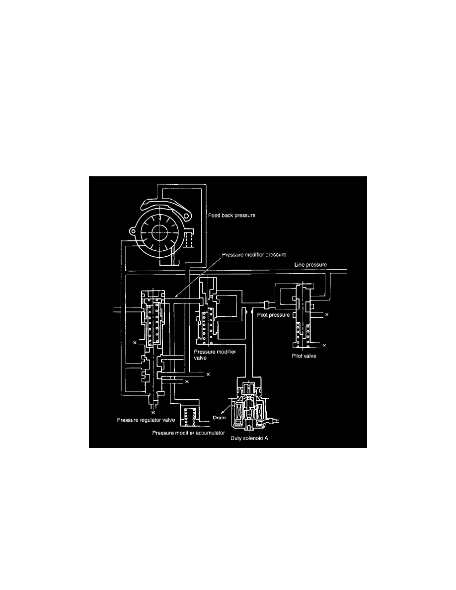
Line-Pressure Control
1. The oil pump delivery pressure (line pressure) is regulated to the constant pilot pressure by the pilot valve.
2. The pilot pressure applied to the pressure modifier valve is regulated by the line pressure controlling duty solenoid A and changed into the
pressure modifier pressure.
3. The pressure modifier valve is an auxiliary valve for the pressure regulator valve, and it creates a signal pressure (pressure modifier pressure) for
regulating the line pressure to an optimum pressure corresponding to the driving conditions.
4. This pressure modifier pressure is applied to the pressure regulator valve to control the oil pump delivery pressure.
5. The delivery pressure of the oil pump is regulated to an appropriate pressure (line pressure) corresponding to the driving condition to reduce the
loss in the oil pump driving time and acceleration shock.
6. The pressure modifier pressure regulated by the pressure modifier valve is smoothed by the pressure modifier accumulator and pulsation in the line
pressure is eliminated.