
Legacy Postal Wagon AWD F4-2.2L SOHC (1998)
Function
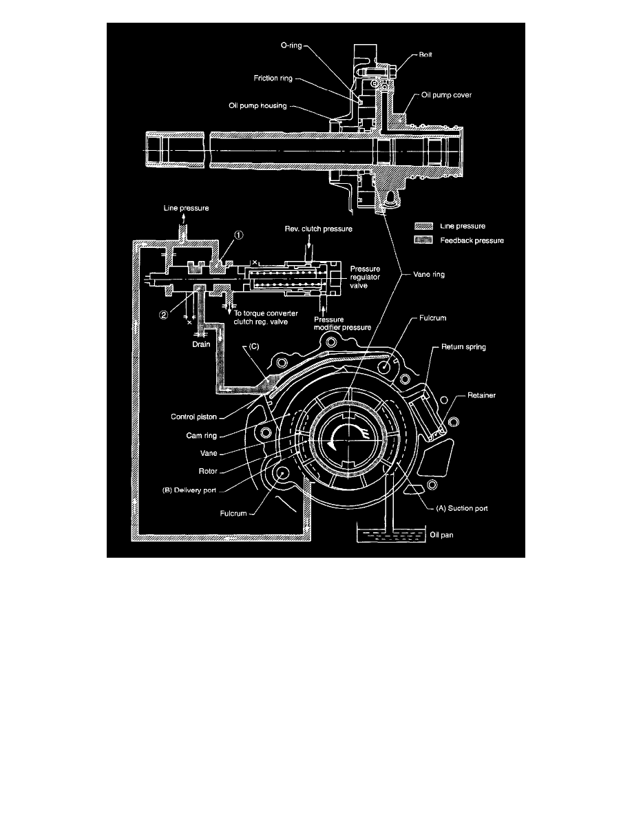
1. The Automatic Transmission Fluid (ATF) is drawn through the oil strainer mounted under the control valve ASSY, and is routed to the
transmission case, to the oil pump housing, and to the oil pump cover. It then goes to the suction port of section A shown in the Figure.
2. The ATF sucked into section A rotates in the direction of the arrow (driven directly by engine), and is compressed at the delivery side of section B.
It is then discharged.
3. The discharged ATF flows from the oil pump cover to the oil pump housing. It then goes to the transmission case, the control valve and to the
regulator valve, thus serving as hydraulic oil and lubricating oil for the torque converter clutch, valves, clutch and brake.
4. As engine speed increases, the delivery rate of the vane pump also increases.
5. Feedback pressure from the regulator valve is applied to section C in the Figure. The cam ring position (the amount of eccentricity) is controlled
by this pressure so that the pump delivery rate remains constant at speeds exceeding the preset pump speed.
6. As the cam ring position changes, the suction volume at section A varies. In this manner, the pump delivery volume is controlled.