
Legacy Wagon 4WD F4-2.2L SOHC (1991)
Brake Fluid Solenoid Valve Relay: Testing and Inspection
Checking Valve Relays
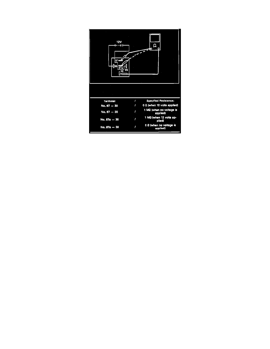
Fig. 33 Valve Relay Test Connection & Specifications
1. Check valve relay coil on ABS control unit by turning ignition off, disconnect and disassemble ABS control unit connector.
2. Measure resistance between hydraulic unit connector P12 terminal 17 and 27 on except SVX models or connector R7, terminal 17 and 27 on SVX
models. Resistance should be 80-90 Ohms.
3. Check hydraulic unit valve relay by measuring resistance between connector F8 terminal 1 on except SVX models or connector R7 terminal one
on SVX models and F9 terminal eight. Resistance should be 2 M Ohm.
4. Check valve relay by attaching test probes to terminals 87 and 87a to terminal 30, Refer to Fig. 33 for specifications.
5. Check hydraulic valve unit by measuring resistance between connector F9 terminals five and seven on except SVX models or connector R1
terminals six and 12 on SVX models. Resistance should be 80 to 90 Ohms.
6. Disconnect connector from ABS and hydraulic units, on except SVX models, measure resistance between connector F9 terminal 5 and P12
terminal 17, and connector F9 terminal 7 and P12 terminal 27. On SVX models, measure resistance between connector R1 terminal 6 and R7
terminal 17, and connector R1 terminal 12 and R7 terminal 27. Resistance should be 0 Ohms.
7. Measure resistance between connector F9 terminal five to ground, then connector F9 terminal seven to ground. The resistance should be 1 M Ohm
minimum.
8. Check and repair power harness by turning off ignition and measuring resistance, between connector F8 and ground on SVX models or between
connector F43 terminal 1 and ground on SVX models. Specifications should be 10 to 12 volts.