
Legacy Wagon 4WD F4-2.5L DOHC (1996)
Check Procedure # 2:
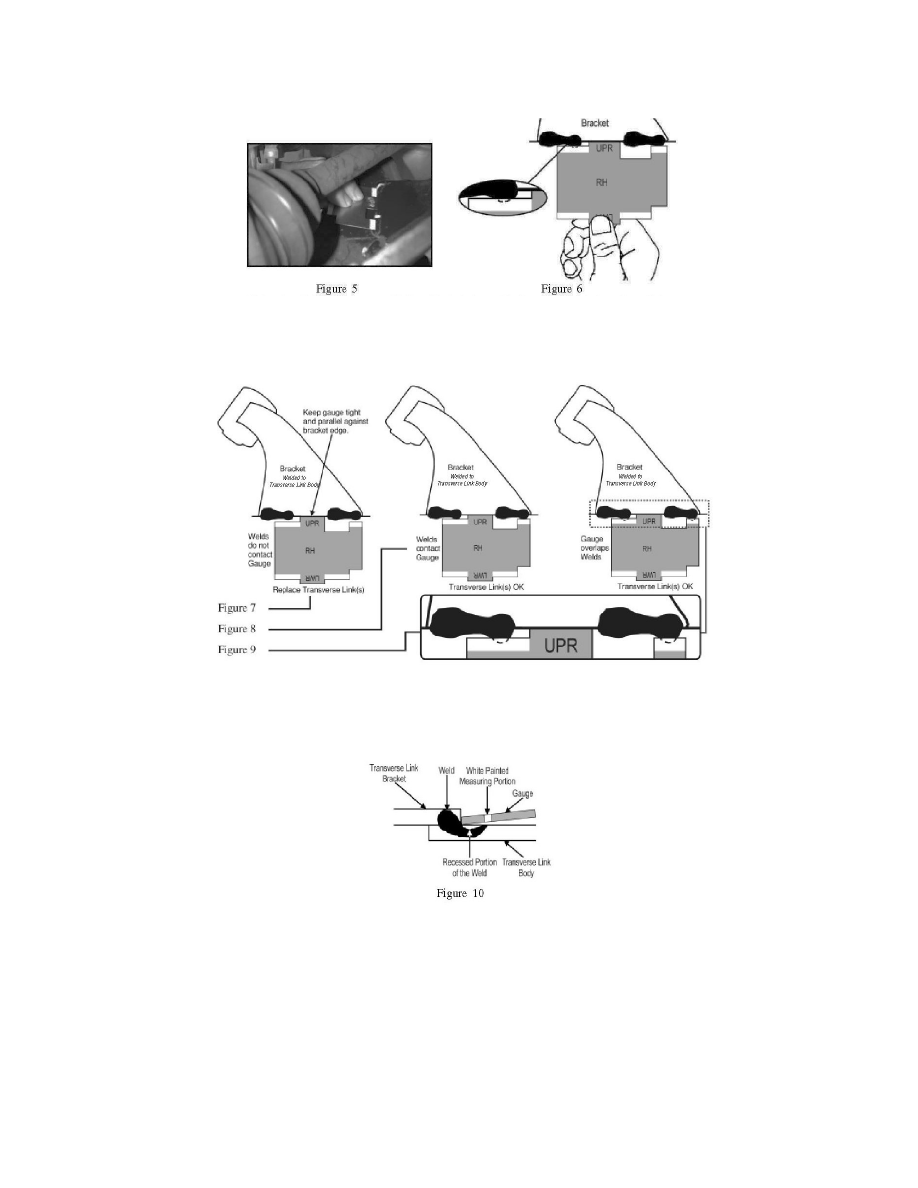
Checking Upper Portion of Transverse Links
Step 1) Use the side marked UPR on the gauge and check the welds of the upper portion on the transverse links (LH and RH). Position the gauge marked
UPR between both welds. Align the edge of the gauge tight and parallel with the transfer link bracket. Refer to figure 5. Keep the rear of the gauge raised
up on a slight angle away from the Transverse Link. This is to prevent any weld flashing bead interference with the gauge. Refer to figure 6.
Step 2) Determine if both Transverse Link welds interfere with the white painted portion of the gauge. If the white painted portions of the gauge contact
or overlap both welds, the Transverse Link(s) are within specification. If the white painted portions of the gauge do not contact or overlap both welds,
replace the Transverse Link(s) following the procedures outlined in the applicable Subaru Service Manuals. Refer to figures 7 through 9.
Note:
If the edges of the welds are recessed in the link and contact or are under the white painted portion of the gauge, this portion of the check is ok. Refer
to figure 10. Make sure the portion of the gauge marked UPR is centered between both welds. Use the RH marked side of the gauge on the right
transverse link and the LH marked side of the gauge on the left transverse link.
Checking Lower Portion of Transverse Links