
Outback F4-2.5L (2008)
Auxiliary Power Outlet: Diagnostic Aids
Basic Procedures
BASIC PROCEDURES
1. GENERAL DESCRIPTION
The most important purpose of diagnostics is to quickly determine which part is malfunctioning, to save time and labor.
2. IDENTIFICATION OF TROUBLE SYMPTOM
Determine what the problem is based on the symptom.
3. PROBABLE CAUSE OF TROUBLE
Look at the wiring diagram and check the system's circuit. Then check the switch, relay, fuse, ground, etc.
4. LOCATION AND REPAIR OF TROUBLE
1. Using the diagnostics, narrow down the causes.
2. If necessary, use a voltmeter, ohmmeter, etc.
3. Before replacing certain component parts (switch, relay, etc.), check the power supply, ground, for open wiring harness, poor connectors, etc.
If no problem is encountered, check the component parts.
5. SYSTEM OPERATION CHECK
After repairing, ensure that the system operates properly.
Basic Inspection
BASIC INSPECTION
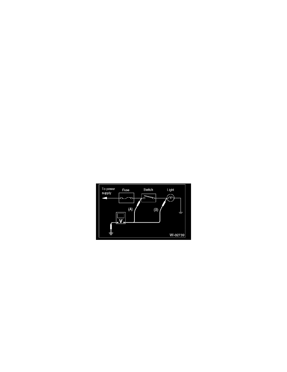
1. VOLTAGE MEASUREMENT
1. Using a voltmeter, connect the negative lead to a good ground point or negative battery terminal and the positive lead to the connector or
component terminal.
2. Contact the positive lead of the voltmeter on connector (A). The voltmeter will indicate a voltage.
3. Shift the positive lead to connector (B). The voltmeter will indicate no voltage.
4. With the test set-up held as it is, turn the switch to ON. The voltmeter will indicate a voltage and, at the same time, the light will illuminate.
5. The circuit is in good order. If a problem such as a light failing to illuminate occurs, use the procedures outlined above to track down the
malfunction.
2. CIRCUIT CONTINUITY CHECKS
1. Disconnect the battery terminal or connector so there is no voltage between the check points. Contact the two leads of an ohmmeter to each of
the check points.
If the circuit has diodes, reverse the two leads and check again.
2. Use an ohmmeter to check for diode continuity. When contacting the negative lead to the diode positive side and the positive lead to the
negative side, there should be continuity.