
Outback F4-2.5L DOHC Turbo (2006)
CAUTION: If brake fluid is spilled on the vehicle body, wash it off immediately with water and wipe clean.
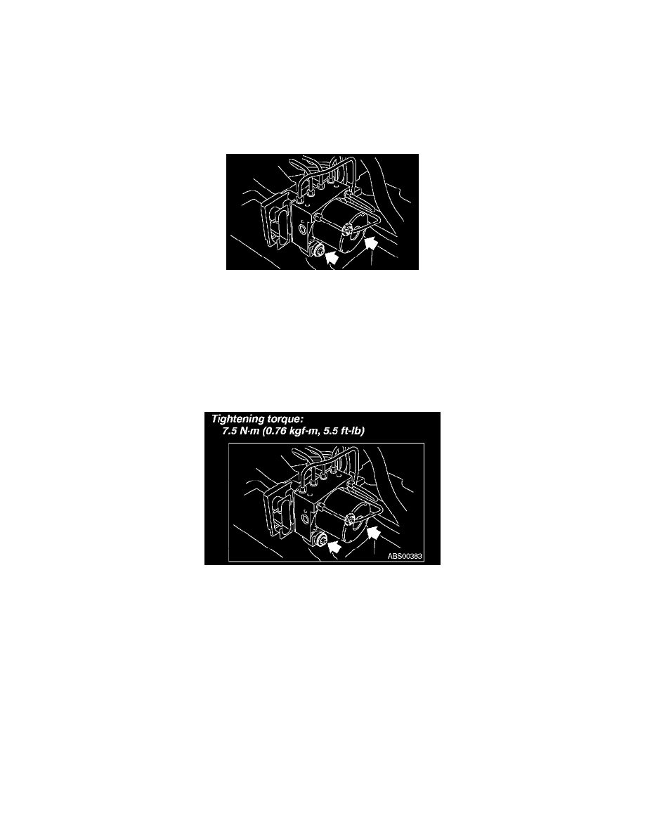
7. Remove the nuts and remove the ABSCM & H/U.
CAUTION:
^
Do not drop or bump the ABSCM & H/U.
^
Do not turn the ABSCM & H/U upside down or place it sideways for storage.
^
Be careful not to let foreign matter enter into ABSCM & H/U.
^
Be careful that no water enters the connectors.
8. Remove the ABSCM & H/U bracket.
INSTALLATION
1. Install the ABSCM & H/U bracket.
Tightening torque: 33 Nm (3.3 kgf-m, 24 ft. lbs.)
2. Install the ABSCM & H/U by aligning the damper groove of the ABSCM & H/U to the bracket side claw.
NOTE: Check the identification marks of the ABSCM & H/U.
3. Connect the brake pipes to their correct ABSCM & H/U positions.
Tightening torque: 15 Nm (1.5 kgf-m, 10.8 ft. lbs.)
4. Using a harness clip, secure the ABSCM & H/U harness to the bracket.
5. Connect the connector to the ABSCM & H/U.
NOTE:
^
Be sure to remove all foreign matter from inside the connector before connecting.
^
Make sure the ABSCM&H/U connector is securely locked.
6. Bleed air from the brake system.
INSPECTION
1. Check the condition of connection and settlement of connector.
2. Check the mark used for ABSCM & H/U identification. Refer to "SPECIFICATION" for the identification mark.