
Outback F6-3.0L DOHC (2006)
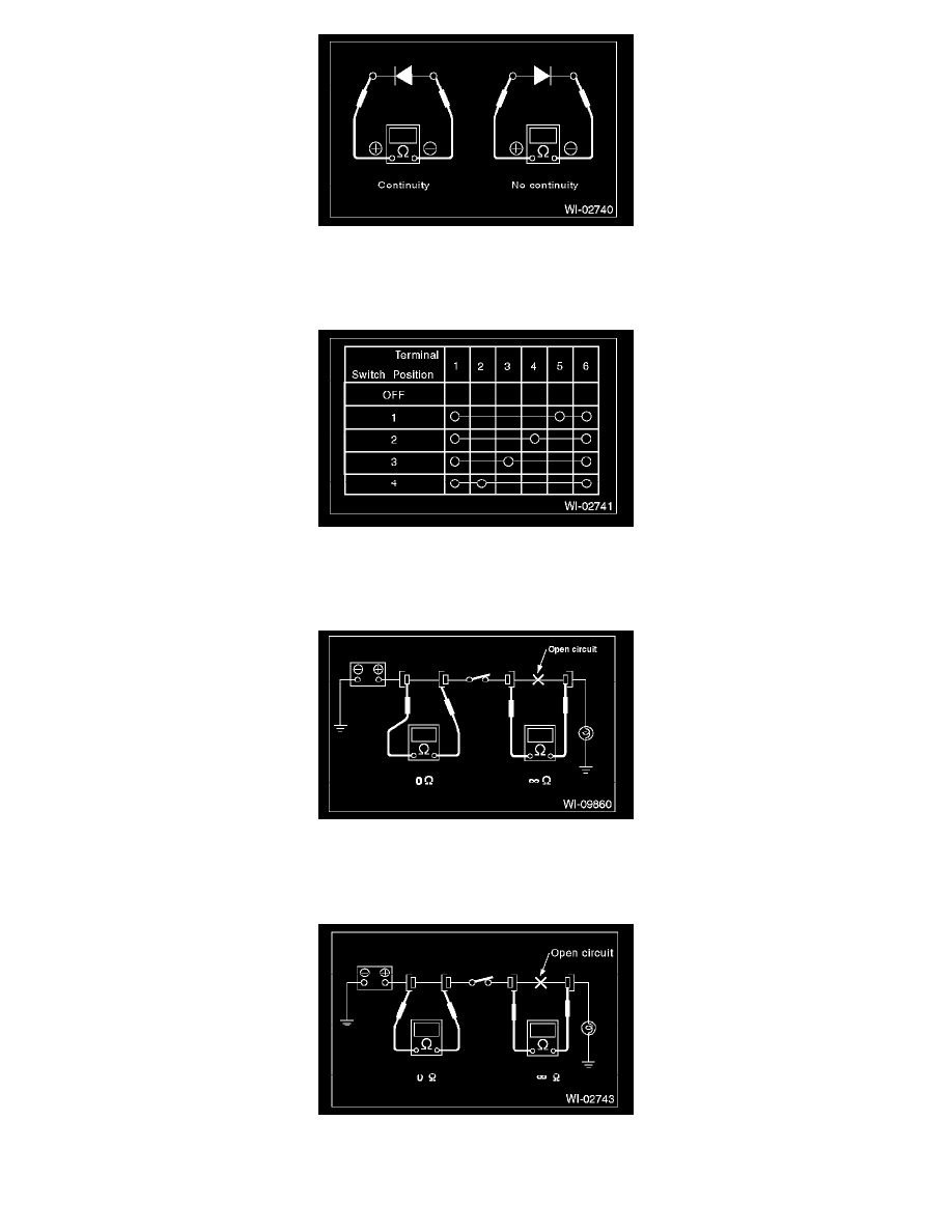
2. Use an ohmmeter to check for diode continuity. When contacting the negative lead to the diode positive side and the positive lead to the
negative side, there should be continuity.
When contacting the two leads in reverse, there should be no continuity.
3. The symbol "O--O" indicates that continuity exists between two points or terminals. For example, when a switch position is at "3", continuity
exists among terminals 1, 3 and 6, as shown in the table.
3. HOW TO DETERMINE AN OPEN CIRCUIT
1. WITH VOLTMETER:
An open circuit is determined by measuring the voltage between respective connectors and ground using a voltmeter, starting with the
connector closest to the power supply. The power supply must be turned ON so that current flows in the circuit. If voltage is not present
between a particular connector and ground, the circuit between that connector and the previous connector is open.
2. WITH OHMMETER:
Disconnect all connectors affected, and check continuity in the wiring between adjacent connectors. When the ohmmeter indicates "infinite",
the wiring is open.