
Outback L.L.Bean Edition AWD F6-3.0L (2002)
Control Module HVAC: Description and Operation
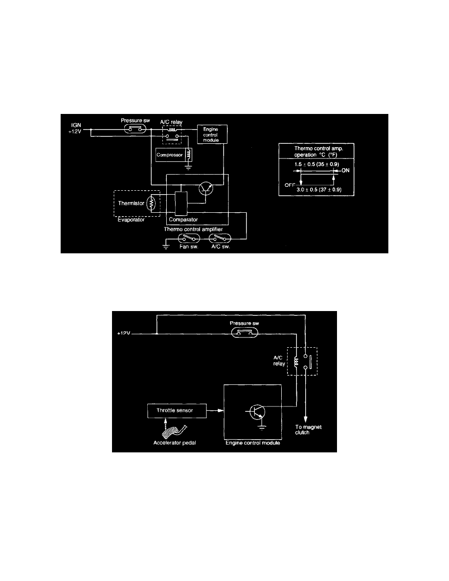
Compressor Control System
Compressor Control System
GENERAL
1. When the A/C switch and fan switch are turned ON, the A/C relay is activated. The compressor starts operating, and then the main and sub fans
also operate.
2. The thermo control amplifier, when activated, disengages the compressor clutch and the main and sub fans.
3. When the pressure switch turns on, the compressor clutch is disengaged and the main and sub fans also stop.
THERMO CONTROL AMPLIFIER
The thermo control amplifier disconnects the magnet clutch circuit to prevent the evaporator from becoming frosted when the temperature of the
evaporator fin drops close to 3 °C (37 °F). When the limit temperature is reached, the thermistor (located on the evaporator fin) interrupts the base
current of the amplifier. This deactivates the A/C relay, which in turn disconnects the magnet clutch circuit.
ACCELERATION CUT SYSTEM
The A/C switch turns the air conditioning system ON and OFF. The on-off signals from the switch are transmitted to the engine control module (ECM).
When the ECM receives a full-throttle signal from the throttle sensor during compressor operation, it deactivates the A/C relay to interrupt electric
current to the compressor magnet clutch. This prevents the degradation of acceleration performance. The A/C relay is in the main fuse box located on the
left side of the engine compartment.