
Outback L.L.Bean Edition AWD F6-3.0L (2002)
Fuel Gauge: Description and Operation
FUEL GAUGE
1. GENERAL
-
The fuel gauge unit consists of a float and a potentiometer whose resistance varies depending on movement of the float. It is located inside the
fuel tank and forms an integral part of the fuel pump. The fuel gauge indicates the fuel level in the tank even when the ignition switch is in the
LOCK position.
-
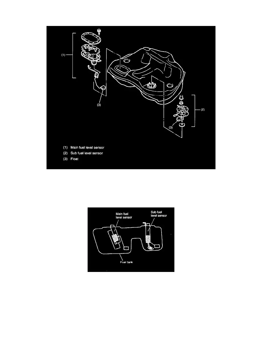
All models are equipped with two fuel level sensors. These sensors are installed in the fuel tank, one on the right side and the other on the left
side. Two sensors are necessary because the fuel tank is divided into main and sub tank compartments.
2. OPERATION
The low fuel warning light operates as follows:
-
The combination meter CPU continually monitors the resistance signal from the fuel level sensor. It turns on the low fuel warning light in the
combination meter if a resistance value corresponding to the critical fuel level (approx. 76 Ohm) is detected successively for about 10 minutes
or the period spent for driving a distance of 10 km.
-
This monitoring time has been decided to avoid false operation of the warning light which may happen when a large part of remaining fuel is
collected temporarily in the sub tank compartment.