
Outback L.L.Bean Edition AWD F6-3.0L (2002)
Axle Shaft: Description and Operation
Front Axle
GENERAL
^
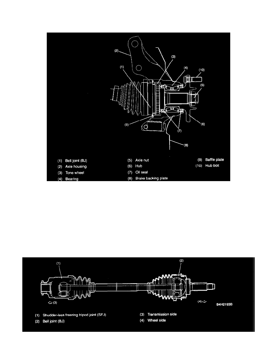
The inboard end of each axle shaft is connected to the transmission via a constant velocity joint (shudder-less free ring tripod joint: SFJ), which is
flexible in the axial directions while the outboard end is connected via a bell joint (BJ) to the wheel hub, which is supported by a taper roller
bearing located inside the axle housing. The BJ features a large operating angle. Both the constant velocity joints (SFJ and BJ) ensure smooth,
regular rotation of the drive wheels with minimum vibration.
^
The bearing is a preloaded, non-adjustable tapered roller unit bearing. Each hub is fitted in the axle housing via the tapered roller bearing.
^
The BJ's spindle is splined to the hub and is secured with an axle nut clinched to it.
^
The disc rotor is an external mounting type. It is secured to the disc wheel using hub bolts to facilitate maintenance of the disc rotor.
1. 3.0 ENGINE MODEL
^
The hubs are induction-hardened.
2. 2.5 ENGINE MODEL
^
The hubs are same as those used in the previous model.
FRONT DRIVE SHAFT
^
A shudder-less free ring tripod joint (SFJ) is used on the differential side of each front drive shaft. The SFJ can be disassembled for maintenance.