
Outback [Legacy] AWD F4-2.5L DOHC (1996)
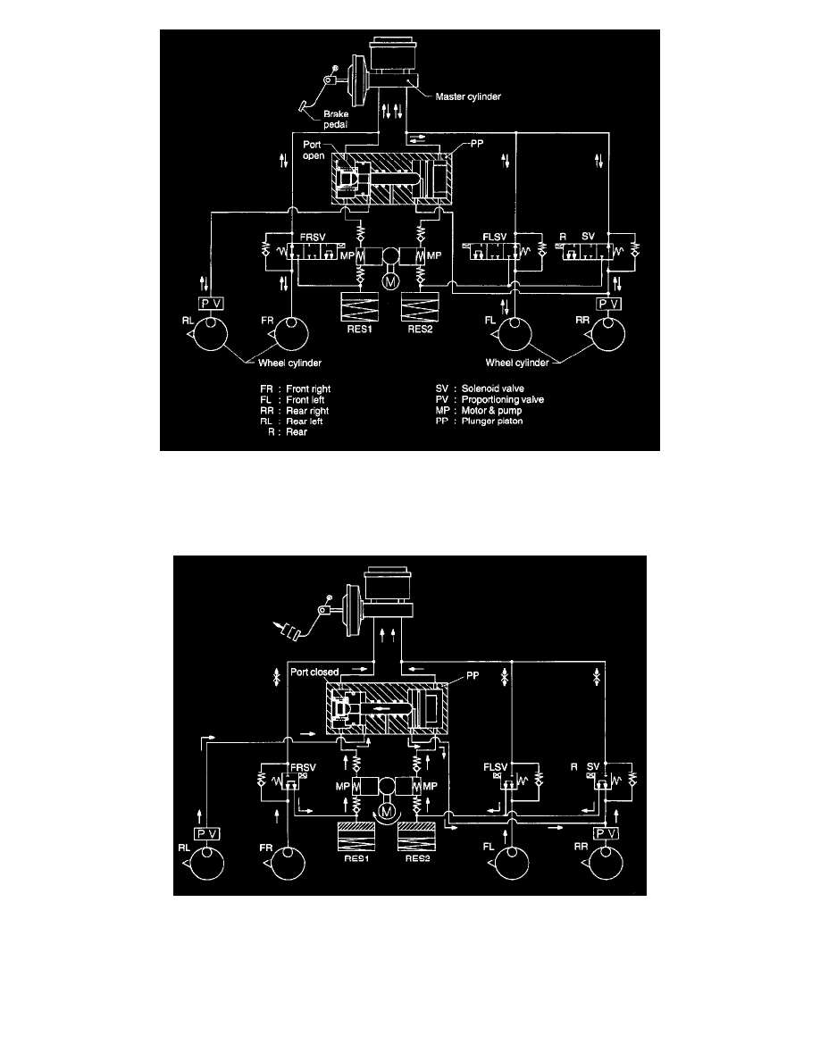
1) During normal braking (Electric current is OFF)
When the brake pedal is depressed, fluid pressure is generated in the master cylinder and is routed to each wheel cylinder [FR (Front right), FL
(Front left), and RR (Rear right)] passing through each solenoid valve [FR, FL, and R (Rear)], causing the brake to work. Pressurized fluid
passes through the port of plunger piston, activating the RL (Rear left) wheel cylinder
Releasing the brake pedal allows fluid pressure in the reverse direction.
2) Pressure "decrease" action with ABS in operation (Electric current is fully ON)
If one wheel shows signs of locking, solenoid valves are controlled under the state of decompression (full electric current) by the ABS control
module, and the inlet port of each solenoid valve is closed while the outlet port is opened. Brake fluid from the FL, FR, and RR wheel
cylinders is released through the outlet port to the reservoir, which decreases the braking force. The unequal fluid pressure in the pressure
chamber at the right side of the plunger piston results in the reduction of the fluid pressure in the RR wheel cylinder by the R (Rear) solenoid
valve, which energizes the plunger piston to move to the left. Upon closing the pressure chamber port on the left side, the side chamber of the
RL wheel cylinder is decompressed.