
Outback [Legacy] AWD F4-2.5L DOHC (1996)
When the solenoid valve is controlled at full electric current, the ABS control module simultaneously sends an electric current to the motor
relay thus driving the motor. Brake fluid in the reservoir is pumped to the damper chamber of the plunger piston by the plunger pump where it
dampens pulsating pressure and then returns to the master cylinder (at this time, the brake pedal feels as if it is pressed back).
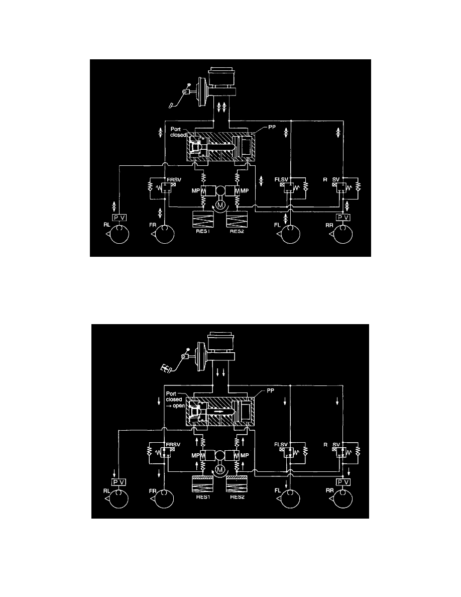
3) Pressure "hold" action with ABS in operation (Halt electric current)
When the fluid pressure in the wheel cylinders is optimally reduced (or increased), the solenoid valve is maintained in a "holding state" (half
electric current) in which both inlet and outlet port are closed. Fluid pressure in the FL, FR, and RR wheel cylinder sides from the solenoid
valve is held in this controlled state. Thus, the fluid pressure generated in the wheel cylinder side from the solenoid valve corresponds to a
force depressing the brake pedal.
Since fluid pressure in the RL wheel cylinder is controlled by the plunger piston, it is kept equal to the pressure in the RR wheel cylinder.
4) Pressure "increase" action with ABS in operation (Electric current is OFF)
As soon as wheel lock is avoided, electric current in the solenoid valve is cut off as instructed by the electronic controller.
Thus, fluid pressure becomes constant from the master cylinder through the FL, FR, and RR wheel cylinders.
The fluid pressure in the master cylinder generated by depressing the brake pedal can pass directly to the FL, FR, and RR wheel cylinders and
reenergize the braking force.