
Outback [Legacy] AWD F4-2.5L DOHC (1996)
Symbol..........................................................................................................................................................................................Wiring harness and Cord
F................................................................................................................................................................................................................Front wiring harness
B.........................................................................................................................................................................................................Bulkhead wiring harness
E.............................................................................................................................................................................................................Engine wiring harness
T...................................................................................................................................................................................................................Transmission cord
D.....................................................................................................................................................................................Door cord LH & RH, Rear gate cord
I..............................................................................................................................................................................................Instrument panel wiring harness
R................................................................................................................................................................................Rear wiring harness, Rear defogger cord
........................................................................................................................................................................................................................Room light cord
............................................................................................................................................................................................................................Fuel tank cord
................................................................................................................................................................................................................................unroof cord
...........................................................................................................................................................................................................................Trunk lid cord
P................................................................................................................................................................................................................Floor wiring harness
General Description
Wiring Diagram
1. WIRING DIAGRAM
The wiring diagram of each system is illustrated so that you can understand the path through which the electric current flows from the battery.
Sketches and codes are used in the diagrams. They should read as follows:
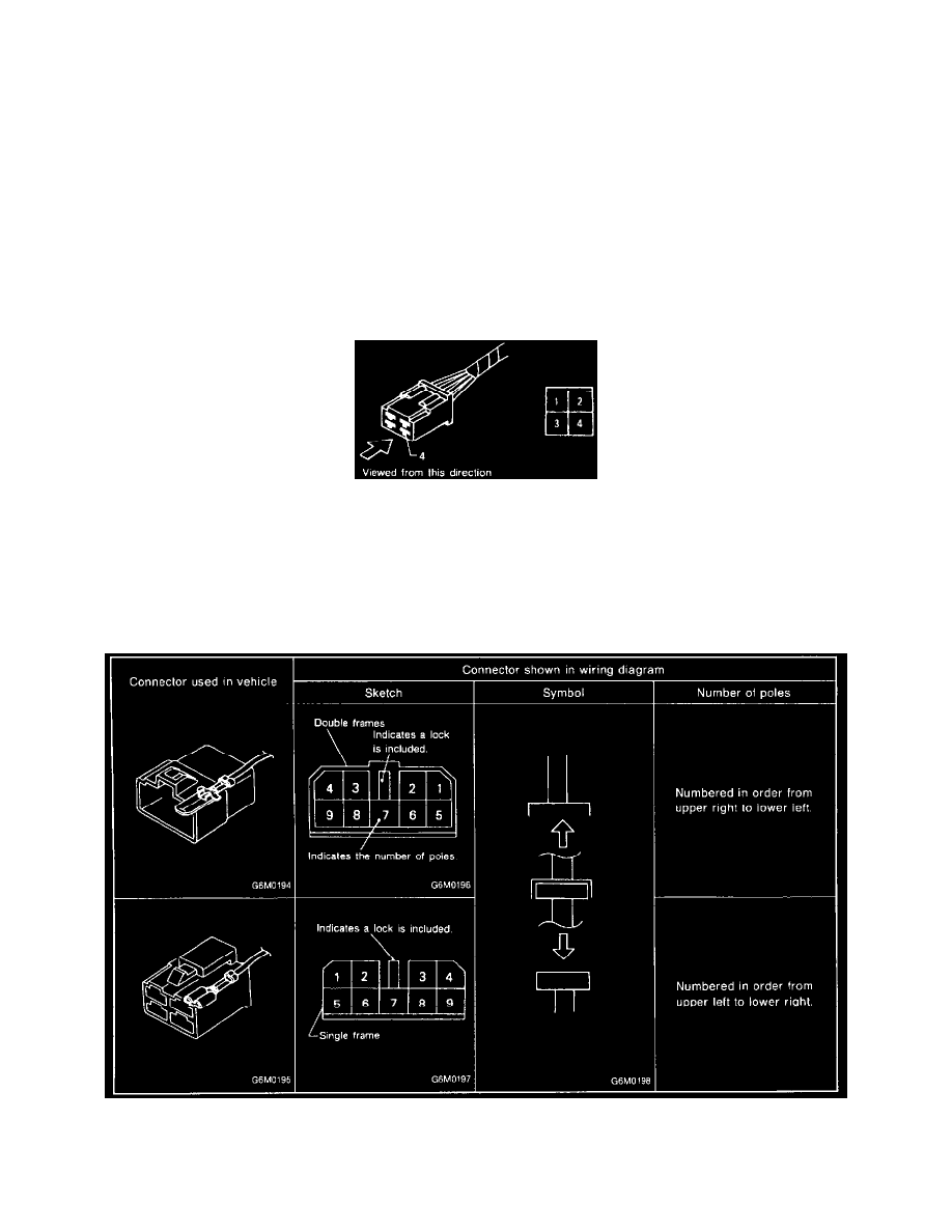
1) Each connector and its terminal position are indicated by a sketch of the connector in a disconnected state which is viewed from the front as
shown in image.
Connectors
2) The number of poles or pins, presence of a lock, and pin number of each terminal are indicated in the sketch of each connector.
In the sketch, the highest pole number refers to the number of poles which the connector has. For example, the sketch of the connector shown