
Outback [Legacy] AWD F4-2.5L DOHC (1996)
in image indicates the connector has 9 poles.
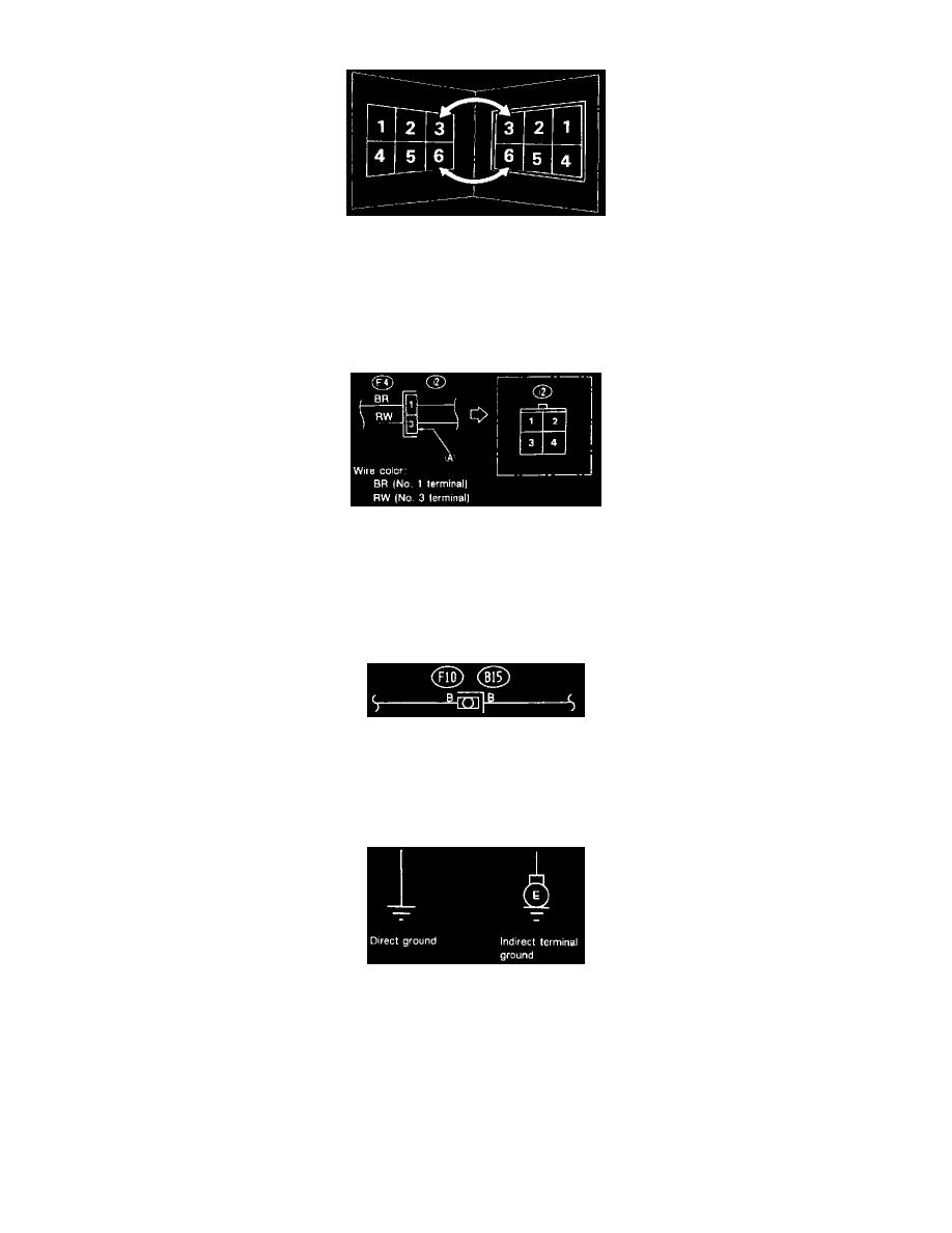
Connectors
When one set of connectors is viewed from the front side, the pole numbers of one connector are symmetrical to those of the other. When these
two connectors are connected as a unit, the poles which have the same number are joined.
3) Electrical wiring harness
The connectors are numbered along with the number of poles, external colors, and mating connections in the accompanying list.
Connectors In Wiring Diagram
4) The sketch of each connector in the wiring diagram usually shows the "A" side of the connector. The relationship between the wire color,
terminal number and connector is described in image.
NOTE: A wire which runs in one direction from a connector terminal sometimes may have a different color from that which runs in the other direction
from that terminal.
Connectors With No Terminal Numbers
5) In wiring diagram, connectors which have no terminal number refer to one-pole types. Sketches of these connectors are omitted intentionally.
Ground Points
Ground Points
Each unit is directly grounded to the body or indirectly grounds through a harness ground terminal. Different symbols are used in the wiring diagram to
identify the two grounding systems.
The ground points shown in the wiring diagram corresponds to the following:
GB Body ground
GE Engine ground
GR Radio ground
GD Rear defogger ground
All wiring harnesses are provided with a ground point which should be securely connected.