
Outback [Legacy] AWD F4-2.5L DOHC (1996)
How To Use Wiring Diagram
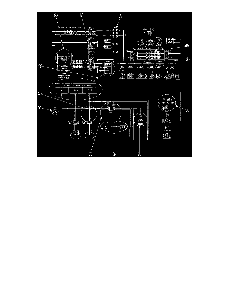
A: Relay
A symbol used to indicate a relay.
B: Connector-1
The sketch of the connector indicates the one-pole types.
C: Wiring Connection
Some wiring diagrams are indicated in foldouts for convenience. Wiring destinations are indicated where necessary by corresponding symbols
D: Fuse No. & Rating
The "FUSE No. & RATING" corresponds that used in the fuse box (main fuse box, and joint box).
E: Connector-2
1. Each connector is indicated by a symbol.
2. Each terminal number is indicated in the corresponding wiring diagram in an abbreviated form.
3. For example, terminal number "C2" corresponds to No. 2 terminal of connector (C:F41) shown in the connector sketch.
F: Connector Sketch
1. Each connector sketch clearly identifies the shape and color of a connector as well as terminal locations. Non-colored connectors are indicated
in natural color.
2. When more than two types of connector number are indicated in a connector sketch, it means that the same type connectors are used.
G: Ground
Each grounding point can be located easily by referring to the corresponding wiring harness.
H: Diode
A symbol is used to indicate a diode.