
Outback [Legacy] AWD F4-2.5L DOHC (1996)
Steering Gear: Description and Operation
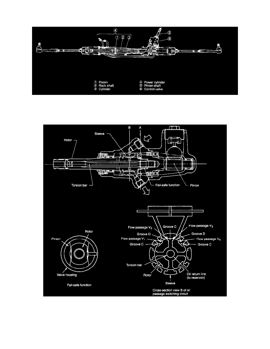
2. GEARBOX ASSEMBLY
1) Power cylinder
The gearbox is integrated with a built-in control valve and power cylinder The rack shaft is used as a power cylinder piston and a rotary
control valve is located in such a manner as to enclose the pinion shaft.
The control valve and power cylinder are connected to each other by two pipes through which hydraulic oil flows.
2) Control valve
The control valve consists of a rotor (which rotates together with the steering shaft), a pinion (which is connected to the rotor and torsion bar),
and a sleeve (which rotates together with the pinion).
Oil grooves C and D are located in the rotor and sleeve to form oil flow passages V1 through V4.
The pinion and rotor are meshed with adequate clearance. They utilize a fail-safe design.