
Outback [Legacy] AWD F4-2.5L DOHC (1996)
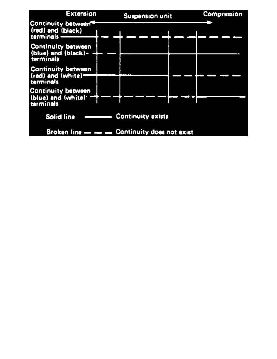
Fig. 3 Vehicle Height Sensor Continuity Chart
Compress and extend from or rear suspension assembly, then check for continuity between suspension assembly harness terminals, Fig. 2.
Continuity should be as described, Fig. 3.
A7 - Leakage Solenoid Valve
With compressed air applied to front or rear suspension system, disconnect air line from air joint furthest from suspension assembly, using tool
No. 926520000, or equivalent, then check for leakage at assembly and solenoid valve.
A8 - Break In Solenoid Valve
Connect a suitable 12 volt source to coupler, then check for operating noise or for continuity between terminals.
A9 - Clogged Air Line
Check for foreign material or twisted lines and repair as necessary.
A10 - Compressor Relay
Connect a suitable 12 volt source to solenoid valve, then apply compressed air and check that air passes through solenoid. If air does not pass
through valve, replace.
A11 - Compressor Malfunction
Connect a suitable 12 volt source to compressor and check for proper operation. If circuit breaker is tripped due to high temperatures, allow
compressor to cool, then operation should return to normal.
A12 - Compressor Relay