
Outback [Legacy] AWD F4-2.5L DOHC (1996)
Transmission Position Switch/Sensor: Diagnostic Aids
Basic Diagnostic Procedures
The most important purpose of diagnostics is to determine which part is malfunctioning quickly, to save time and labor.
A. Identification Of Trouble Symptom
Determine what the problem is based on the symptom.
B. Probable Cause Of Trouble
Look at the wiring diagram and check the system's circuit. Then check the switch, relay, fuse, ground, etc.
C. Location And Repair Of Trouble
1) Using the diagnostics narrow down the causes.
2) If necessary, use a voltmeter, ohmmeter, etc.
3) Before replacing certain component parts (switch, relay, etc.), check the power supply, ground, for open wiring harness, poor connectors, etc.
If no problems are encountered, check the component parts.
D. Confirmation Of System Operation
After repairing, ensure that the system operates properly.
Circuit Continuity Checks
Circuit Continuity Checks
1) Disconnect the battery terminal or connector so there is no voltage between the check points.
Contact the two leads of an ohmmeter to each of the check points.
If the circuit has diodes, reverse the two leads and check again.
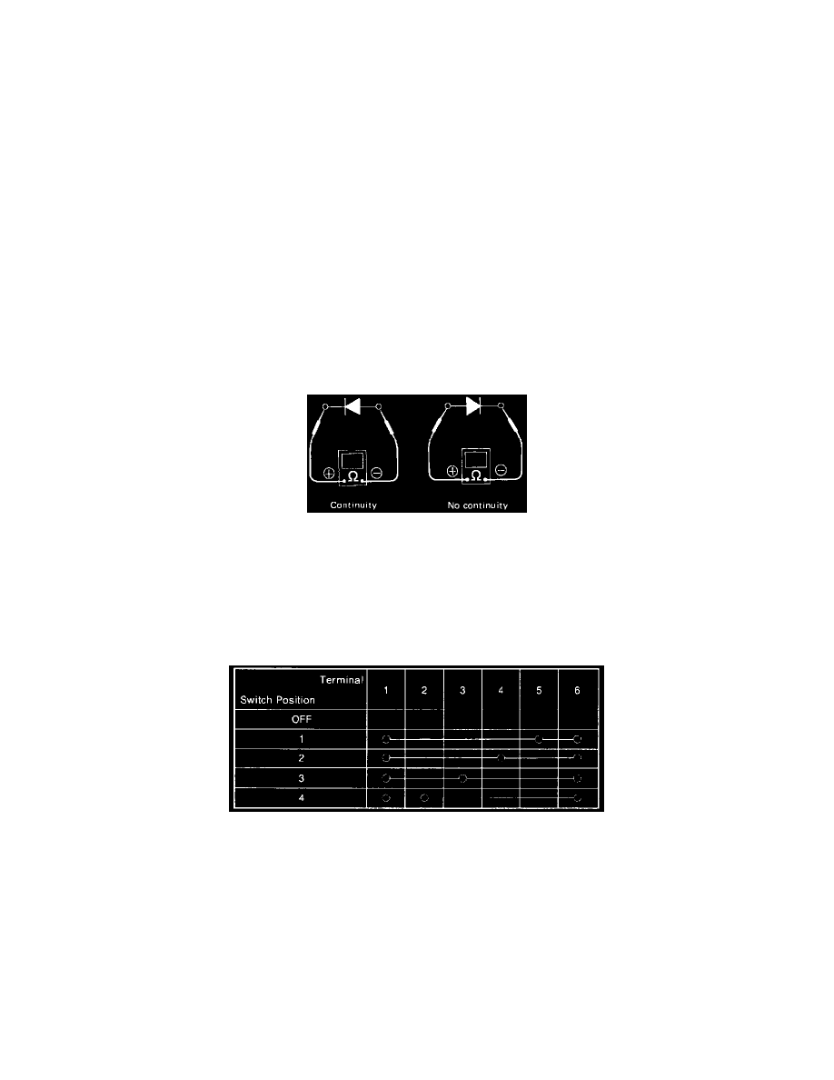
2) Use an ohmmeter to check for diode continuity.
When contacting the negative lead to the diode positive side and the positive lead to the negative side, there should be continuity.
When contacting the two leads in reverse, there should be no continuity.
Circuit Continuity Checks
3) Symbol "o__o" indicates that continuity exists between two points or terminals. For example, when a switch position is "3", continuity exists
among terminals 1, 3 and 6, as shown in the image.
How to Determine A Short Circuit