
Outback Sport F4-2.5L SOHC (2005)
1. WIRING DIAGRAM
The wiring diagram of each system is illustrated so that you can understand the path through which electric current flows from battery.
Sketches and codes are used in the diagrams. They should read as follows:
-
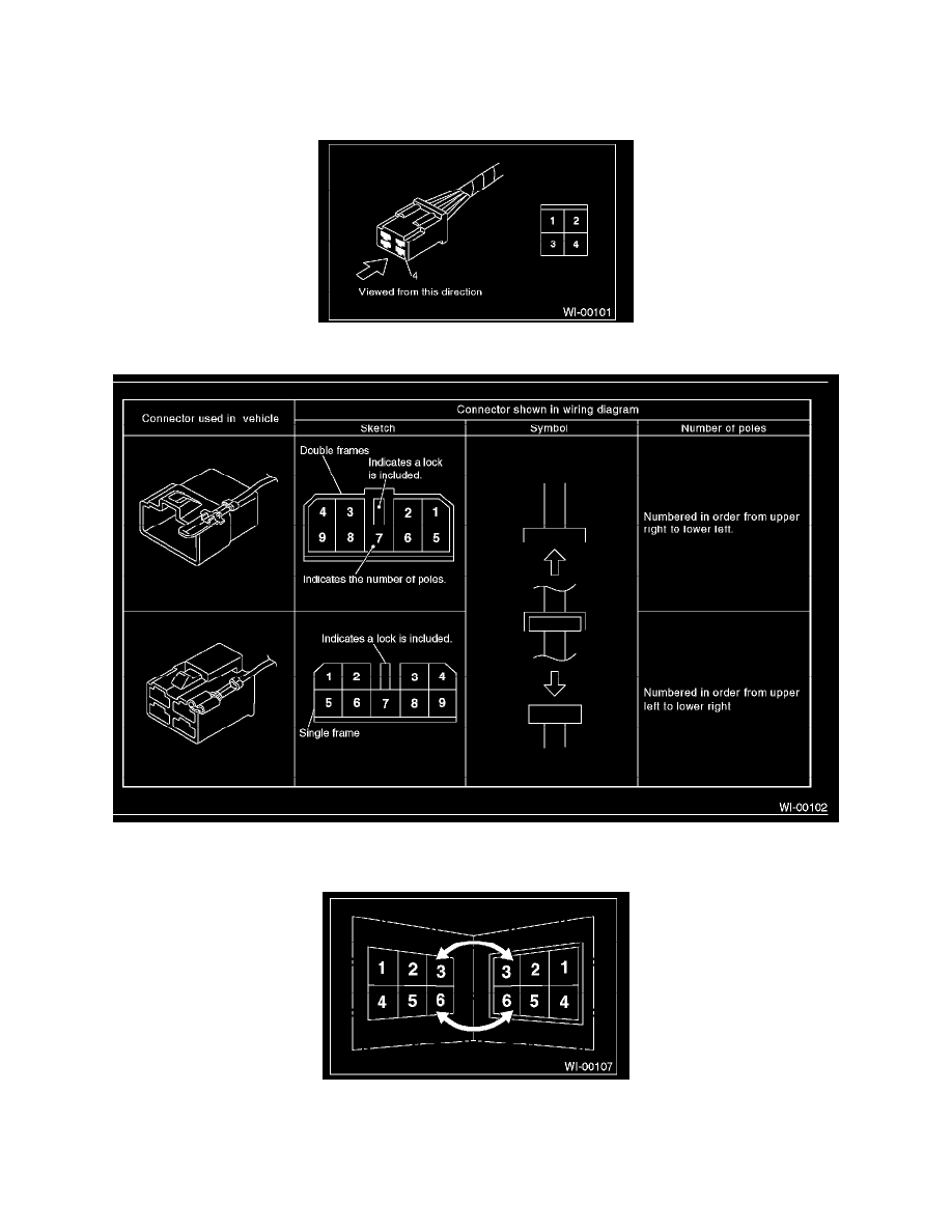
Each connector and its terminal position are indicated by a sketch of the connector in a disconnected state which is viewed from front.
-
The number of poles or pins, presence of a lock are indicated in the sketch of each connector. In the sketch, the highest pole number refers to
the number of poles which connector has. For example, the sketch of connector shown in the figure indicates the connector has 9 poles.
-
When one set of connectors is viewed from the front side, the pole numbers of one connector are symmetrical to those of other. When these
two connectors are connected as a unit, the poles which have the same number are joined.
-
WIRING DIAGRAM:
The connectors are numbered along with the number of poles, external colors, and mating connections in accompanying list.