
SVX AWD L6-3.3L DOHC (1995)
Diagnostic Chart
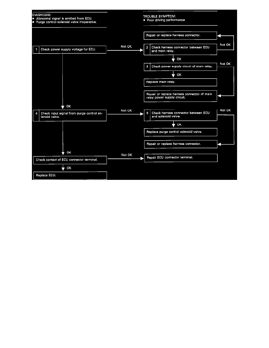
CANISTER PURGE SOLENOID DIAGNOSTIC CHART
1. CHECK ECU VOLTAGE
a.
With ignition "ON," measure voltage between ECU and ground.
Connector (terminal)
Voltage
B62(14) & ground
min 10 VDC
Should read 10-13V.
2. CHECK HARNESS CONNECTOR BETWEEN ECU AND MAIN RELAY
a.
Turn ignition "OFF".
b.
Disconnect ECU and main relay connectors.
c.
Measure resistance between ECU connector and relay connector.
Connector (terminal)
Resistance
B62(14) & B52(4)
0 ohms
3. CHECK POWER SUPPLY TO MAIN RELAY
a.
Turn ignition "ON".
b.
Disconnect main relay connector.
c.
Measure voltage between relay connector and ground.
Connector (terminal)
Voltage
B52(1) & ground
min 10 VDC
B52(2) & ground
min 10 VDC
4. CHECK INPUT SIGNAL FROM PURGE CONTROL SOLENOID
a.
Turn ignition "ON".
b.
Disconnect main ECU connector.
c.
Measure voltage between ECU connector and ground.