
SVX FWD L6-3.3L DOHC (1994)
EGR Temperature Sensor: Testing and Inspection
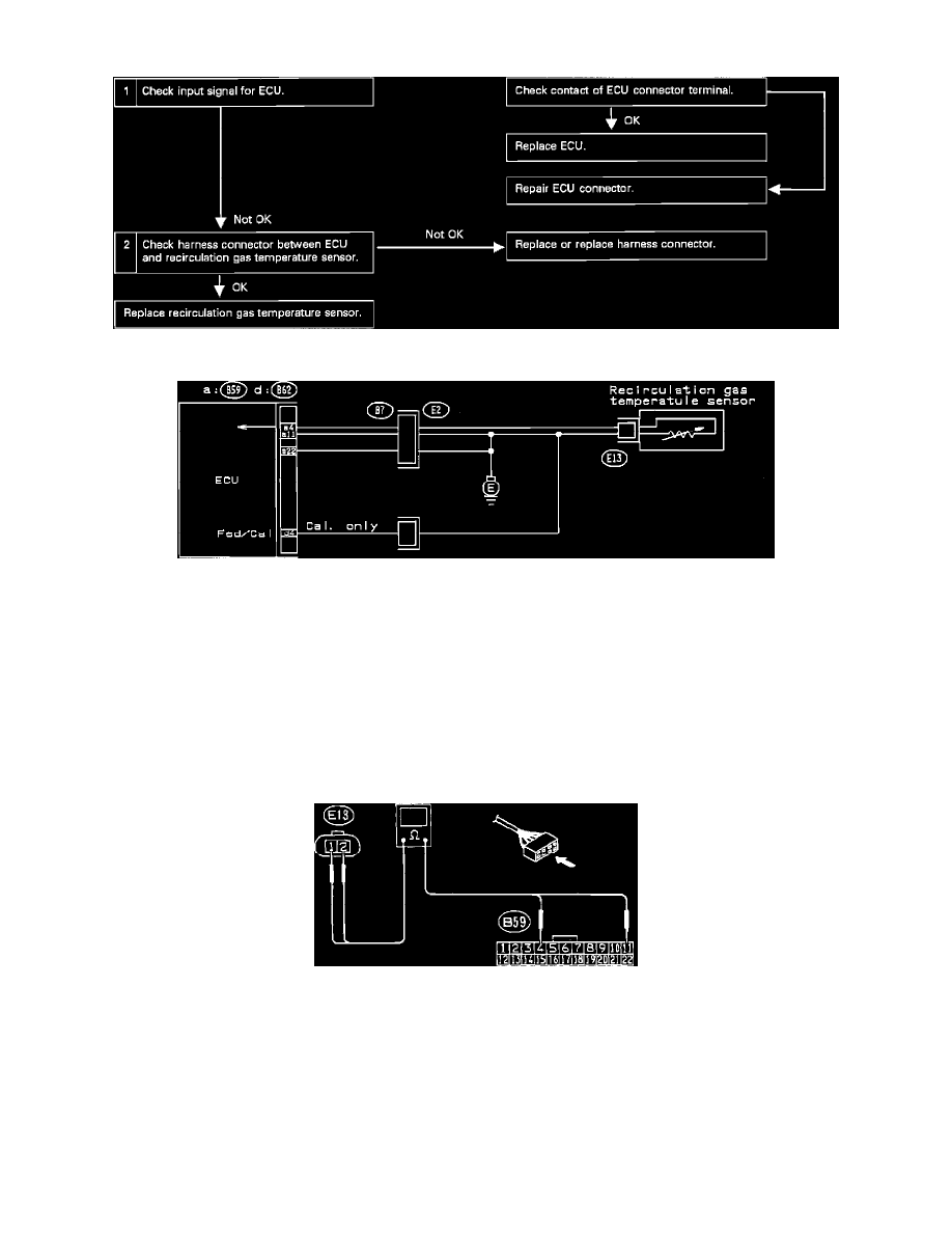
Diagnostic Chart
Wiring Diagram
DIAGNOSTIC CHART AND DIAGRAM
1.
CHECK INPUT SIGNAL FROM SENSOR
1) Turn ignition "ON".
2) Disconnect main ECU connector.
3) Measure voltage between ECU connector and ground.
Connector & Terminal/Specified value
(B59) No. 4 - ground/4.0 - 4.8 vdc @ 68° F (20° C)
(B59) No. 4 - ground/0.4 - 1.2 vdc @ 212° F (100° C)
Harness
2.
CHECK HARNESS CONTINUITY BETWEEM ECU AND SENSOR
1) Turn ignition "OFF".
2) Disconnect ECU and sensor connectors.
3) Measure resistance between ECU connector and sensor connector.
Connector & Terminal/Specified value
(B59) No. 4 - (E13) No. 2/0 ohms
(B59) No. 11 - (E13) No. 1/0 ohms