
Tribeca F6-3.6L (2008)
Hydraulic Control Assembly - Antilock Brakes: Testing and Inspection
VDC Control Module & Hydraulic Control Unit (VDCCM & H/U)
INSPECTION
1. Check the condition of connection and settlement of connector.
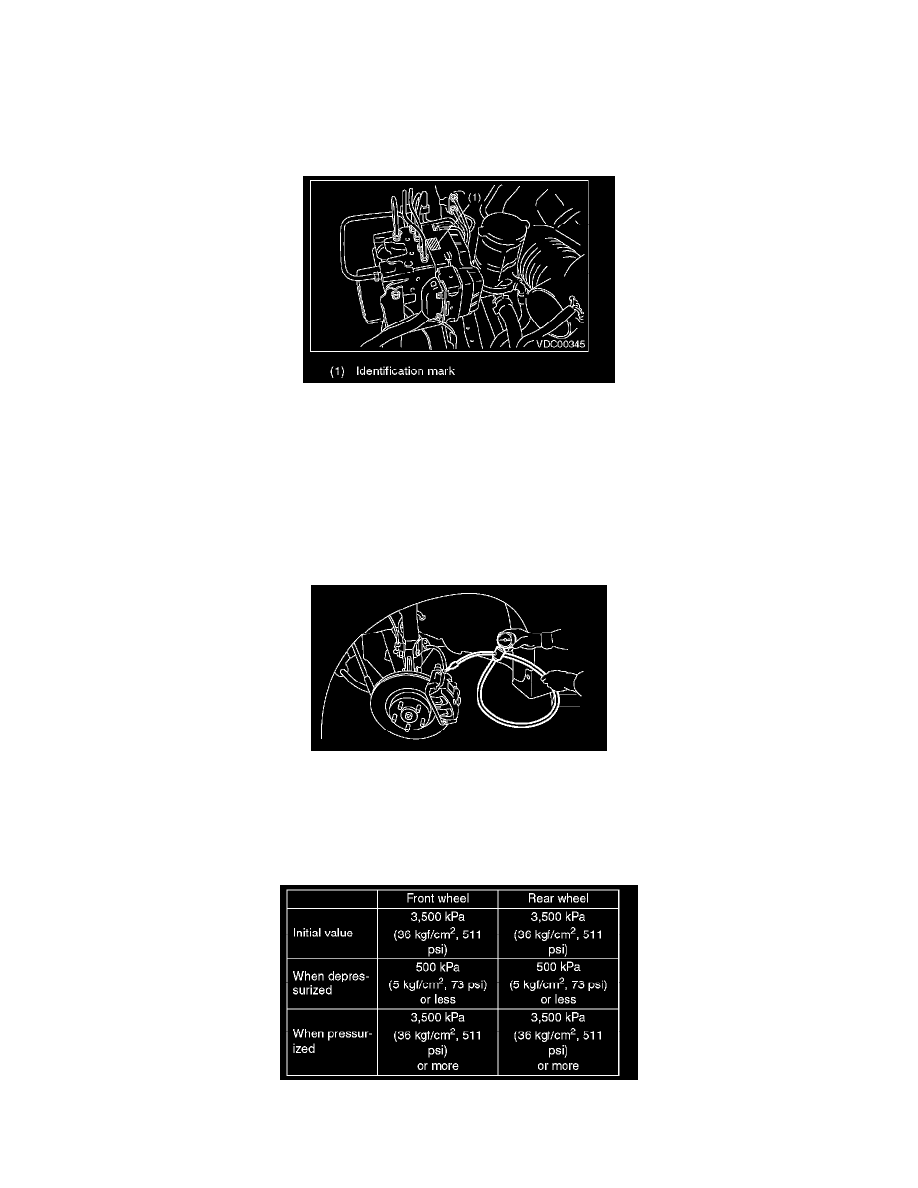
2. Check the mark used for VDCCM&H/U identification.
Refer to SPECIFICATION for the identification mark.
CHECKING THE HYDRAULIC UNIT ABS OPERATION BY PRESSURE GAUGE
1. Lift-up the vehicle and remove the wheel.
2. Remove the air bleeder screws from FL and FR caliper bodies.
3. Connect two pressure gauges to FL and FR caliper bodies.
CAUTION:
^
Use a pressure gauge used exclusively for brake fluid measurement.
^
Do not use the pressure gauge used for the measurement of transmission oil. Doing so will cause the piston seal to expand and deform.
NOTE: Wrap sealing tape around the pressure gauge.
4. Bleed air from the pressure gauges and the FL and FR caliper bodies.
5. Perform ABS sequence control.
6. When the hydraulic unit begins to work, first the FL side performs decompression, hold and compression, and then the FR side performs
decompression, hold and compression.
7. Read values indicated on the pressure gauge and check if the fluctuation of the values between decompression and compression meets the standard
values. Depress the brake pedal and check that the kick-back is normal, and tightness is normal.
8. Disconnect the pressure gauges from FL and FR caliper bodies.
9. Install the air bleeder screws of FL and FR caliper bodies.
10. Remove the air bleeder screws from RL and RR caliper bodies.