
Tribeca F6-3.6L (2008)
4. Bleed air from the pressure gauges and the FL and FR caliper bodies.
5. Perform ABS sequence control.
6. When the hydraulic unit begins to work, first the FL side performs decompression, hold and compression, and then the FR side performs
decompression, hold and compression.
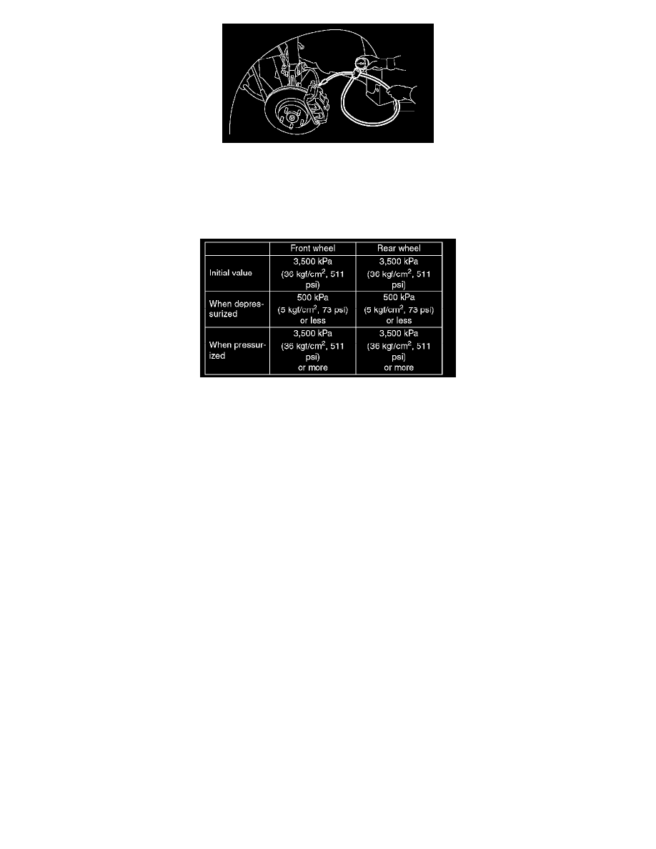
7. Read values indicated on the pressure gauge and check if the fluctuation of the values between decompression and compression meets the standard
values. Depress the brake pedal and check that the kick-back is normal, and tightness is normal.
8. Disconnect the pressure gauges from FL and FR caliper bodies.
9. Install the air bleeder screws of FL and FR caliper bodies.
10. Remove the air bleeder screws from RL and RR caliper bodies.
11. Connect two pressure gauges to RL and RR caliper bodies.
12. Bleed air from the brake system.
13. Bleed air from RL and RR caliper bodies, and pressure gauge.
14. Perform ABS sequence control.
15. When the hydraulic unit begins to work, first the RR side performs decompression, hold and compression, and then the RL side performs
decompression, hold and compression.
16. Read values indicated on the pressure gauge and check if the fluctuation of the values between decompression and compression meets
specification. Depress the brake pedal and check that the kick-back is normal, and tightness is normal.
17. Disconnect the pressure gauge from the RL and RR caliper bodies.
18. Install the air bleeder screws of RL and RR caliper bodies.
19. Bleed air from the brake system.
CHECKING THE HYDRAULIC UNIT ABS OPERATION WITH THE BRAKE TESTER
1. Set wheels other than the one to measure free rollers.
2. Prepare for the ABS sequence control operation.
3. Set the front wheels or rear wheels on the brake tester and set the select lever position to the N range.