
Aerio L4-2.3L (2006)
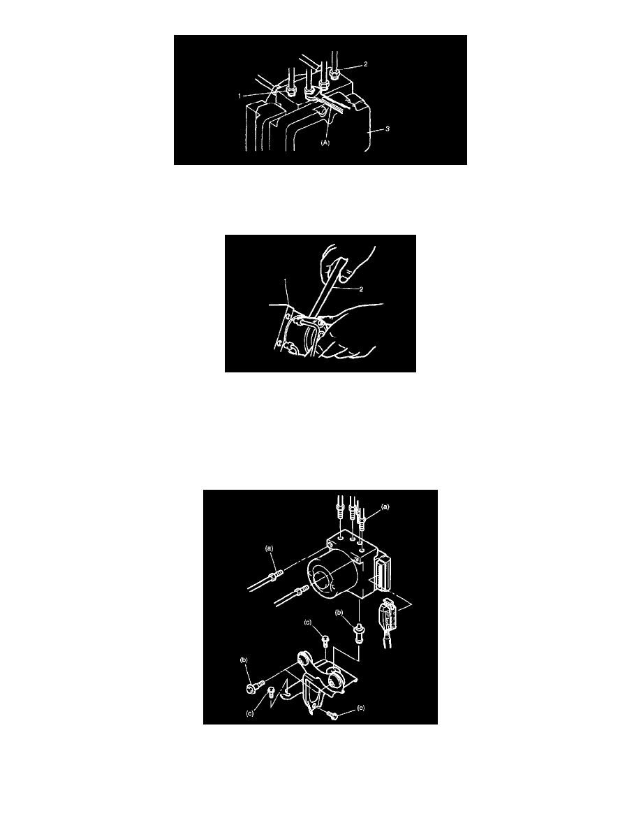
3. Using special tool, loosen flare nuts (1) and disconnect brake pipes (2) from ABS hydraulic unit/control module assembly (3).
Special tool: (A): 09950-78220
NOTE: Put bleeder plug cap or the like onto pipe to prevent fluid from spilling. Do not allow brake fluid to get on painted surfaces.
4. Remove two bolts and disconnect take out ABS hydraulic unit/control module assembly (1) from bracket using flat end rod or the like (2)
CAUTION:
^
Do not give an impact to hydraulic unit.
^
Use care not to allow dust to enter hydraulic unit.
^
Do not place hydraulic unit on its side or upside down. Handling it in inappropriate way will affect its original performance.
Installation
1. Install hydraulic unit/control module assembly by reversing removal procedure.
Tightening torque
Brake pipe flare nut (a): 16 Nm (1.6 kgf-m, 11.5 ft. lbs.)
ABS hydraulic unit/control module assembly bolt (b): 9 Nm (0.9 kgf-m, 6.5 ft. lbs.)
ABS hydraulic unit/control module assembly bracket bolt (c): 23 Nm (2.3 kgf-m, 16.5 ft. lbs.)