
Aerio L4-2.3L (2006)
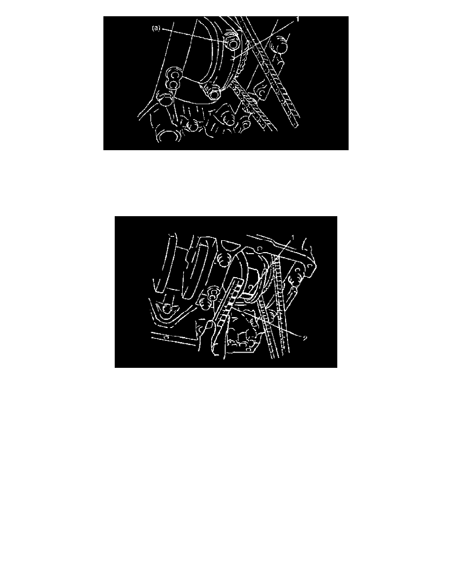
d. Install rod bearing cap to connecting rod. When installing cap, be sure to point arrow mark (1) on cap to crankshaft pulley side, as shown in the
figure. After applying engine oil to rod bolts, tighten cap nuts to specified torque.
Tightening torque
Connecting rod bearing cap nuts (a): 45 Nm (4.5 kgf-cm, 33.0 ft. lbs.)
NOTE: DO NOT turn crankshaft with gauging plastic installed.
e. Remove cap and using a scale (2) on gauging plastic envelope, measure gauging plastic (1) width at the widest point (clearance).
If clearance exceeds its limit, use a new standard size bearing.
After selecting new bearing, recheck clearance.
Connecting rod bearing clearance
Standard: 0.045 - 0.063 mm (0.0018 - 0.0024 inch)
Limit: 0.08 mm (0.0031 inch)
f.
If clearance can not be brought to within its limit even by using a new standard size bearing, replace crankshaft or regrind crankpin to
undersize as follows.
^
Install 0.25 mm undersize bearing to connecting rod big end.
^
Measure bore diameter of connecting rod big end.
^
Regrind crankpin to the finished diameter.
Finished crankpin diameter = Measured big end bore diameter (including undersize bearing - 0.054 mm (0.0021 inch)
^
Confirm that bearing clearance is within the standard value.
Selection of connecting rod bearings
NOTE:
^
If bearing is in malcondition, or bearing clearance is out of specification, select a new standard bearing and install it.
^
When replacing crankshaft or connecting rod and its bearing due to any reason, select new standard bearings to be installed by referring to
numbers stamped on connecting rod and its cap and/or alphabets stamped on crank web of No. 3 cylinder.