
Aerio L4-2.3L (2006)
Throttle Position Sensor: Testing and Inspection
Throttle Position (TP) Sensor On-Vehicle Inspection
Using SUZUKI Scan Tool
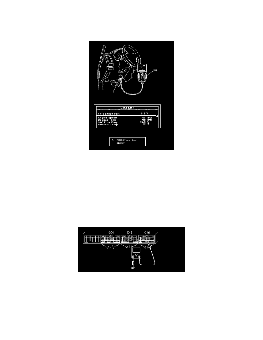
1. Connect SUZUKI scan tool to DLC (1) with ignition switch OFF.
2. Check "TP Sensor Volt" value displayed on scan tool under the following each condition. If measured value is out of specified range, check TP
sensor. If OK, check wire harness of TP sensor.
Also check that "TP Sensor Volt" value varies according to throttle valve opening linearly. If not, it is possible that TP sensor has failed. Replace.
Special Tool
(A): SUZUKI scan tool
TP sensor voltage
When throttle is fully close: 0.70 ± 0.15 V
When throttle is fully open: 4.0 ± 0.5 V
Not Using SUZUKI Scan Tool
1. Remove ECM.
2. Connect couplers to ECM.
3. Using voltmeter, check voltage at "C46-22" terminal under the following each condition. If measured value is out of specified range, check TP
sensor.
If OK, check wire harness of TP sensor.
Also check that voltage varies according to throttle valve opening linearly. If not, it is possible that TP sensor has failed. Replace.
TP sensor voltage
When throttle is fully close: 0.70 ± 0.15 V
When throttle is fully open: 4.0 ± 0.5 V
4. Upon completion of checking, install ECM.