Aerio L4-2.3L (2006)

Fluid Pressure Sensor/Switch: Testing and Inspection
Pressure Control Solenoid Valve Inspection
Reference: Solenoid Valves (Shift Solenoid Valves, TCC Solenoid Valve and Pressure Control Solenoid Valve) Removal and Installation
Resistance Check
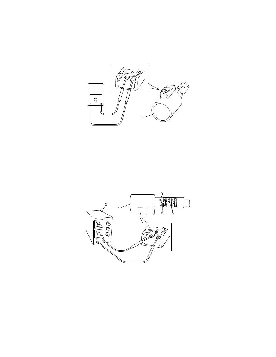
Check resistance between pressure control solenoid valve (1) terminals. If check result is not as specified, replace solenoid valve.
Pressure control solenoid valve resistance
Standard: 5.0 - 5.6 ohms (at 20°C (68°F))
Operation Check
Check pressure control solenoid valve operation in the either manner of the following.
Using regulated DC power supply
1. Connect pressure control solenoid valve (1) with regulated DC power supply (2) as shown in the figure.
2. Turn regulated DC power supply switch ON and increase voltage of power supply keeping current within 1.0 A.
3. Check for gradual movement of valve (3) in the direction of arrow A as voltage is increased.
4. Check movement of valve (3) in the direction of arrow B as voltage is decreased.
5. Turn power supply switch OFF.
CAUTION: Do not pass current 1.0 A or more, or pressure control solenoid is burned out.
Not using regulated DC power supply
1. Connect pressure control solenoid valve (1) to battery (2) setting the 8 - 10 W bulb (4) on the way as shown in the figure.
2. Check for movement of valve (3) in the direction of arrow A.
3. Disconnect pressure control solenoid valve (1) from battery (2) and check movement of valve (3) in the direction of arrow B as shown in the
figure.
CAUTION: Set 8 - 10 W bulb on the way, or pressure control solenoid valve is burned out.
