
Aerio AWD L4-2.0L (2003)
4. Using continuity check or voltage check the following procedure, check the wire harness for open circuit (2) and poor connection with its
terminals. Locate abnormality, if any.
Continuity Check
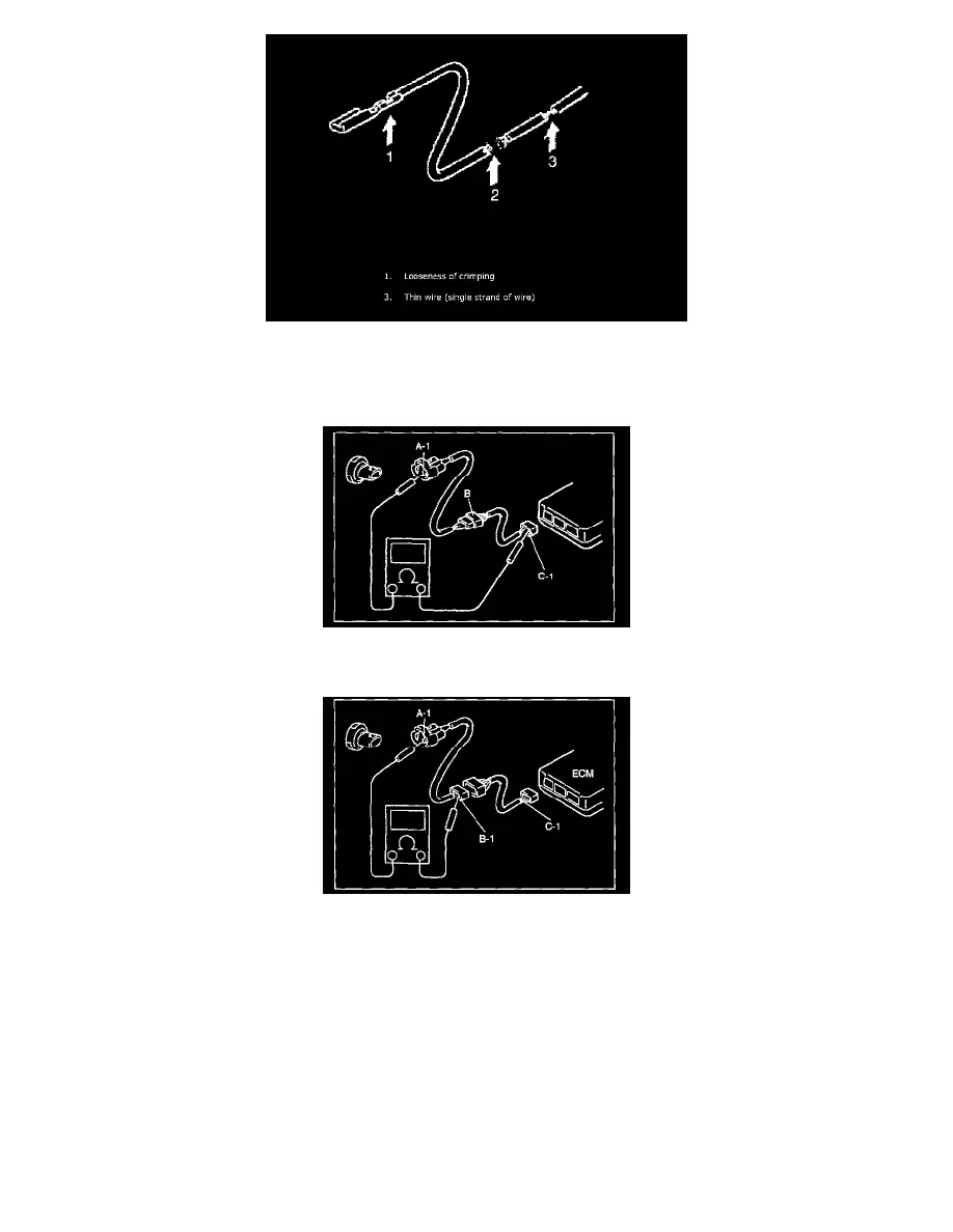
1. Measure resistance between connector terminals at both ends of the circuit being checked (between A-1 and C-1 in the figure). If no continuity is
indicated (infinity or over limit), that means that the circuit is open between terminals A-1 and C-1.
2. Disconnect the connector included in the circuit (connector-B in the figure) and measure resistance between terminals A-1 and B-1. If no
continuity is indicated, that means that the circuit is open between terminals A-1 and B-1. If continuity is indicated, there is an open circuit
between terminals B-1 and C-1 or an abnormality in connector-B.
Voltage Check
If voltage is supplied to the circuit being checked, voltage check can be used as circuit check.
1. With all connectors connected and voltage applied to the circuit being checked, measure voltage between each terminal and body ground.
a. If measurements were taken as shown in the figure and results were as listed in the following, it means that the circuit is open between
terminals B-1 and A-1.
Voltage between
C-1 and body ground: Approx. 5 V
B-1 and body ground: Approx. 5 V
A-1 and body ground: 0 V