
Equator 2WD V6-4.0L (2009)
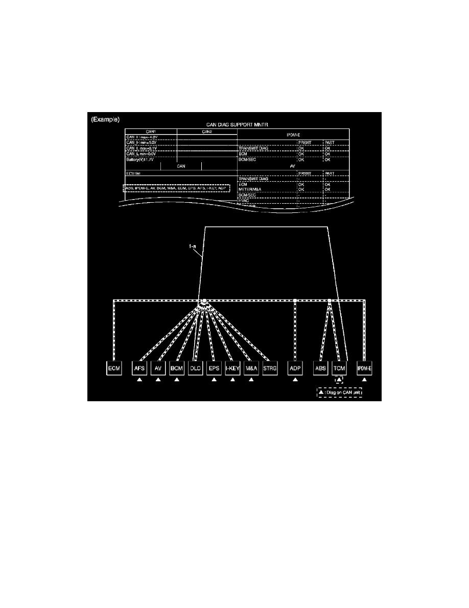
NOTE: CAN communication line has no error if units other than Diag on CAN units are not indicated. An error may be on the power supply of
the control unit, DDL1 line or DDL2 line.
a. "TCM" which is Diag on CAN unit, is not indicated on "ECU list". This indicates that DLC is not receiving a signal from TCM. Draw a line to
indicate an error between DLC and TCM (line 1-a in the figure below).
NOTE:
-
Diag on CAN units are not indicated on the "ECU list" when the CAN line between Diag on CAN unit and the data link connector is open.
-
For a description of Diag on CAN, refer to [DIAG On CAN: Description].
2. Bus check: Check each item on "Bus check". Draw a line on the diagnosis sheet to indicate the error circuit.
a. Reception item of "ECM": On "TCM", "UNKWN" is indicated. This means ECM cannot receive the signal from TCM. Draw a line to indicate
an error between ECM and TCM (line 2-a in the figure below).
NOTE: If "UNKWN" is indicated on "TRANSMIT DIAG", then the control unit cannot transmit CAN communication signal to each unit.
Draw a line between the control unit and the splice.
b. Reception item of "AFS": On "TCM", "UNKWN" is indicated. This means AFS cannot receive the signal from TCM. Draw a line to indicate
an error between AFS and TCM (line 2-b in the figure below).
c. Reception item of "AV": "UNKWN" is not indicated. This indicates normal communication between AV and its receiving units. Do not draw
any line.