
Equator 2WD V6-4.0L (2009)
Input/Output Signal Chart
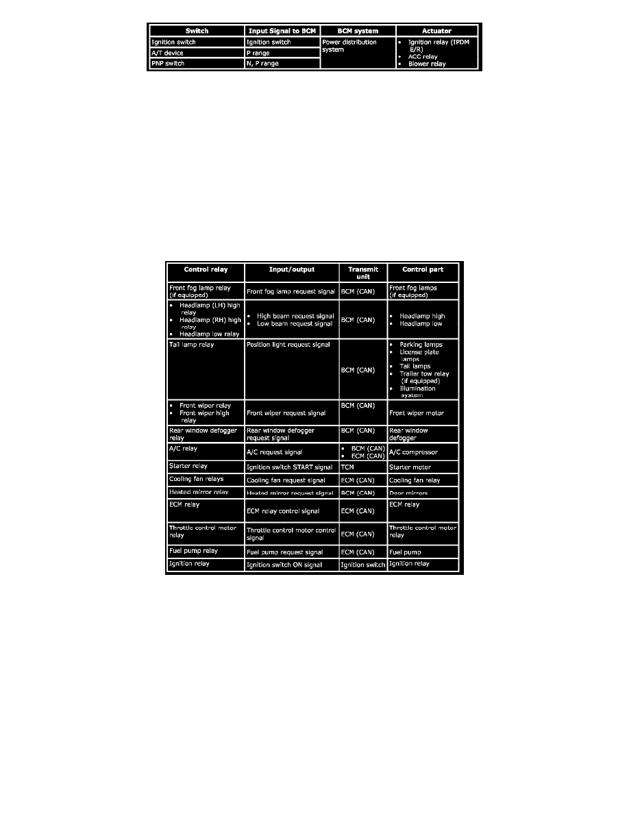
SYSTEM DESCRIPTION
-
PDS (POWER DISTRIBUTION SYSTEM) is the system that BCM controls with the operation of the ignition switch and performs the power
distribution to each power circuit.
-
The ignition switch operation is input to BCM as a signal. BCM changes the power supply position according to the status and operates the
ignition relay (inside IPDM E/R) to supply power to each power circuit.
Relay Control System: System Description
Relay Control System: System Description
IPDM E/R activates the internal control circuit to perform the relay ON-OFF control according to the input signals from various sensors and the request
signals received from control units via CAN communication.
CAUTION: IPDM E/R integrated relays cannot be removed.
Signal Buffer System: System Description
Signal Buffer System: System Description
IPDM E/R reads the status of the oil pressure switch and transmits the oil pressure switch signal to BCM via CAN communication. Refer to [CAN
Communication System: System Description].