
Equator 4WD V6-4.0L (2010)
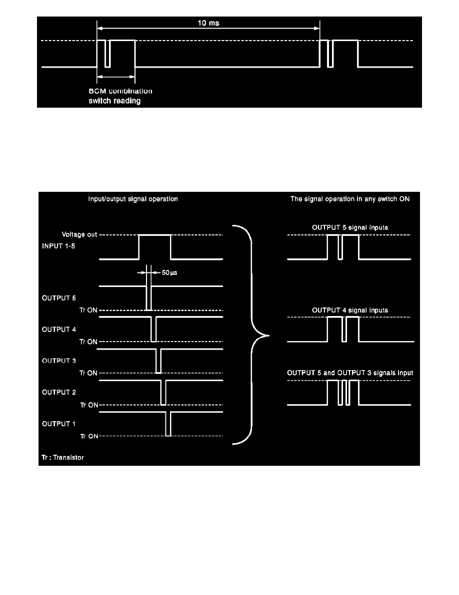
NOTE: BCM reads the status of the combination switch at 20ms interval when BCM is controlled at low power consumption control mode.
-
BCM operates as follows and judges the status of the combination switch.
-
INPUT 1 - 5 outputs the voltage waveforms of 5 systems simultaneously.
-
It operates the transistor on OUTPUT side in the following order: OUTPUT 5 -> 4 -> 3 -> 2 -> 1.
-
The voltage waveform of INPUT corresponding to the formed circuit changes according to the operation of the transistor on OUTPUT side if
any (1 or more) switches are ON.
-
It reads this change of the voltage as the status signal of the combination switch.
Operation Example
In the following operation example, the combination of the status signals of the combination switch is replaced as follows: INPUT 1 - 5 to "1 - 5" and
OUTPUT 1 - 5 to "A - E".
Example 1: When a switch (TURN RH switch) is turned ON
-
The circuit between INPUT 1 and OUTPUT 5 is formed when the TURN RH switch is turned ON.