Equator 4WD V6-4.0L (2010)

-
Insert it while matching it to the axial center.
-
Insert fuel injector so that protrusion of fuel tube matches cutout of clip.
-
Make sure that fuel tube flange is securely fixed in flange fixing groove on clip.
c. Make sure that installation is complete by checking that the fuel injector does not rotate or come off.
-
Make sure that protrusions of the fuel injectors are aligned with cutouts of clips after installation.
4. Connect the fuel tube (RH) to the fuel tube (LH), and tighten bolts temporarily.
-
Tighten bolts to the specified torque after installing fuel tube and fuel injector assembly.
CAUTION:
-
Handle O-ring with bare hands. Do not wear gloves.
-
Lubricate O-ring with new engine oil.
-
Do not clean O-ring with solvent.
-
Make sure that O-ring and its mating part are free of foreign material.
-
When installing O-ring, be careful not to scratch it with tool or fingernails.
-
Do not twist or stretch O-ring. If O-ring was stretched while it was being attached, allow it to retract before inserting it into fuel
tube.
-
Insert new O-ring straight into fuel tube. Do not angle or twist it.
5. Install fuel tube and fuel injector assembly to intake manifold.
CAUTION: Do not let the tip of the injector nozzle come in contact with other parts.
-
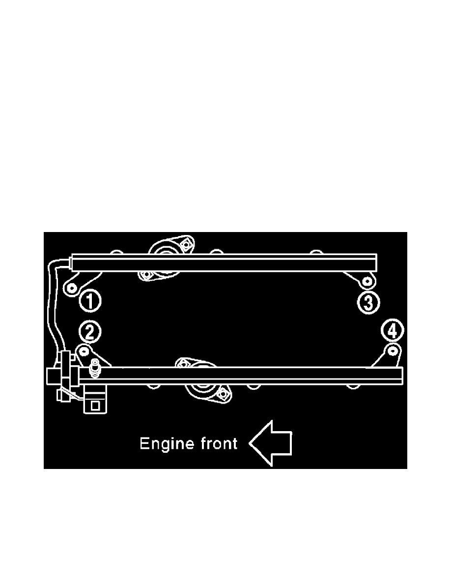
Tighten bolts in two steps in numerical order as shown.
Fuel injector tube assembly bolts
1st step : 10.1 N.m (1.0 kg-m, 7 ft-lb)
2nd step : 22.0 N.m (2.2 kg-m, 16 ft-lb)
6. Tighten bolts which connect fuel tube (RH) and fuel tube (LH) to the specified torque.
7. Connect fuel injector harness connector.
8. Install intake manifold collector. Refer to [Intake Manifold Collector: Removal and Installation].
9. Installation of the remaining components is in the reverse order of removal.
Inspection after Installation
