
Equator 4WD V6-4.0L (2010)
-
BCM detects the combination switch status signal "1E" when the signal of OUTPUT 5 is input to INPUT 1.
-
BCM judges that the TURN RH switch is ON when the signal "1E" is detected.
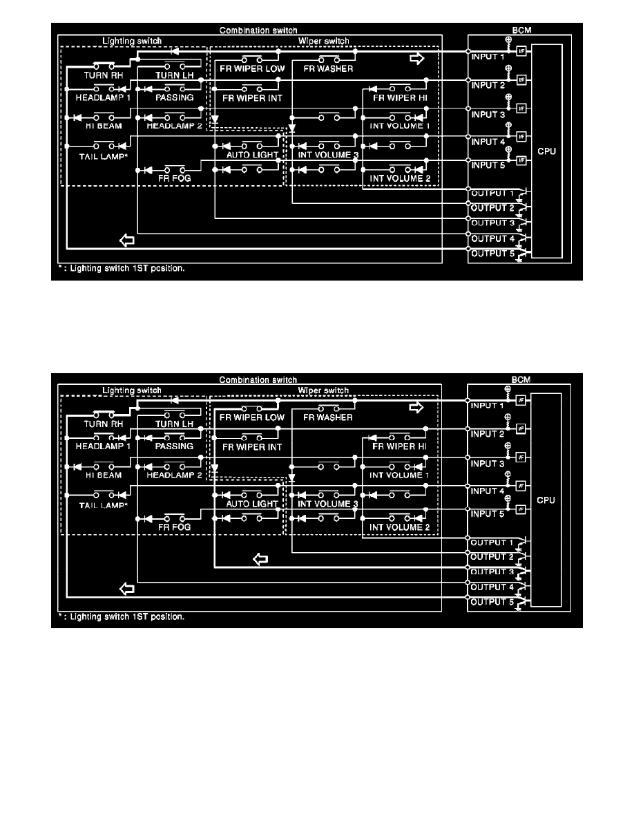
Example 2: When some switches (turn RH switch, front wiper LO switch) are turned ON
-
The circuits between INPUT 1 and OUTPUT 5 and between INPUT 1 and OUTPUT 3 are formed when the TURN RH switch and FR WIPER
LOW switch are turned ON.
-
BCM detects the combination switch status signal "1CE" when the signals of OUTPUT 3 and OUTPUT 5 are input to INPUT 1.
-
BCM judges that the TURN RH switch and FR WIPER LOW switch are ON when the signal "1CE" is detected.
Wiper Intermittent Dial Position Setting (Front Wiper Intermittent Operation)
BCM judges the wiper intermittent dial 1 - 7 by the status of INT VOLUME 1, 2 and 3 switches.