
Esteem L4-1590cc 1.6L SOHC 0 MFI 16V (1995)
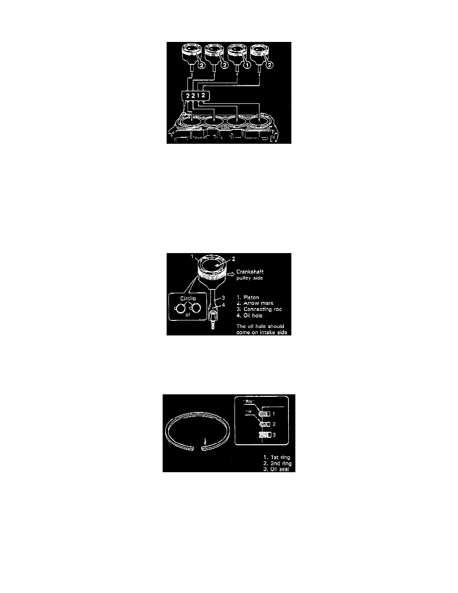
c. Stamped number on piston and that on cylinder block should correspond. That is, install number 2 stamped piston to cylinder which is
identified with number 2 and a number 1 piston to cylinder with number 1.
Piston Outer diameter
1 Mark: 74.98 - 74.99 mm (2.9520 - 2.9524 inch)
2 Mark: 74.97 - 74.98 mm (2.9516 - 2.9520 inch)
Cylinder Bore diameter
1 Mark: 75.01 - 75.02 mm (2.9531 - 2.9535 inch)
2 Mark: 75.00 - 75.01 mm (2.9528 - 2.9531 inch)
Piston-to-cylinder clearance
1 Mark: 0.02 - 0.04 mm (0.0008 - 0.0015 inch)
2 Mark: 0.02 - 0.04 mm (0.0008 - 0.0015 inch)
Also, a letter A, B or C is stamped on piston head but ordinarily it is not necessary to discriminate each piston by this letter.
1. Install piston pin to piston and connecting rod:
After applying engine oil to piston pin and piston pin holes in piston and connecting rod, fit connecting rod to piston as shown in image and insert
piston pin to piston and connecting rod, and install piston pin circlips.
NOTE: Circlip should be installed with its cut part facing either up or down as shown in image.
2. Install piston rings to piston:
-
As indicated in image, 1st and 2nd rings have "RN", "T" or "R" mark respectively. When installing these piston rings to piston, direct marked
side of each ring toward top of piston.
-
1st ring differs from 2nd ring in thickness, shape and color of surface contacting cylinder wail.
Distinguish 1st ring from 2nd ring by referring to image.
-
When installing oil ring, install spacer first and then two rails.