
Esteem GLX Wagon Plus L4-1.6L (1998)
Inspection of Motor
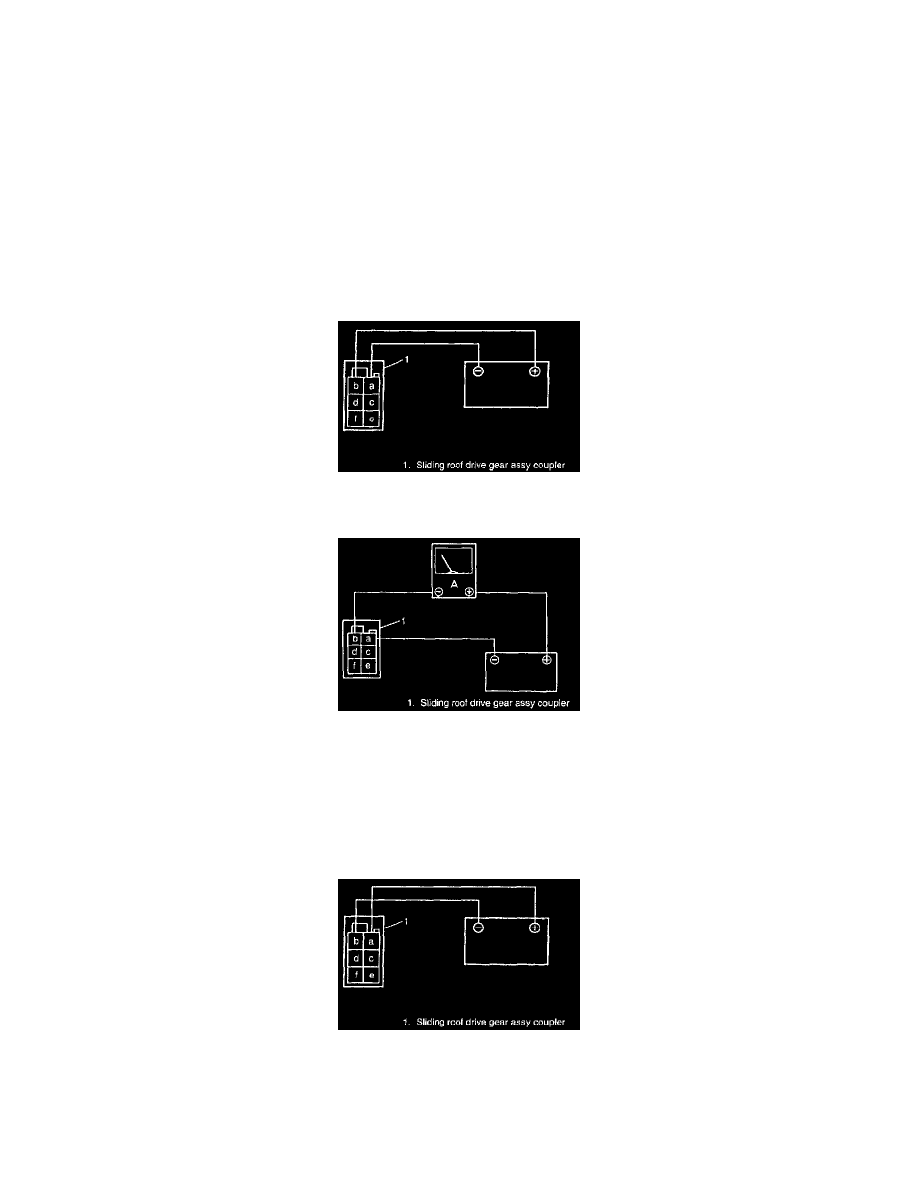
1) Disconnect sliding roof drive gear assy coupler.
2) Connect (+) battery lead to terminal a and (-) battery lead to terminal band check that the motor turns to the left (close/up direction).
3) Reverse polarity (connect (-) battery lead to terminal a and (+) battery lead to terminal b) and check that the motor turns to the right (open/down
direction).
4) If motor does not operate as above 2) and 3) replace it.
Inspection for noise-protection ground
1) Check that the continuity exists between terminal c and the body of motor.
CIRCUIT BREAKER
NOTE: This inspection must be done with the complete sliding roof assembly installed on the vehicle.
1) Disconnect coupler from sliding roof drive gear assy.
2) Connect (-) Battery lead to terminal a, (+) battery lead to terminal b, then open sliding roof completely.
3) Disconnect (-) battery lead from terminal a.
4) Connect ammeter between terminal b and (+) battery lead.
5) Measure time that the current falling down around 16A - 23A to 0A when (-) battery lead connected terminal a again.
Standard measured time: 10-60 sec
If measured time is out of specification, replace sliding root drive gear assy.
6) When the current reaches 0A, disconnect both terminal a and b from battery lead.
7) 60 seconds after the disconnection of terminal a and b, connect (+) battery lead to terminal a, (-) battery lead to terminal b and check that the
sliding roof operates to closing direction.
LIMIT SWITCH 1 AND LIMIT SWITCH 2